| #12 Mechanical Analysis of Unilateral Distal Extension Partial Denture Design |
||
| Y. Ohno, R. Kanbara, Y. Nakamura, K. Shoji, H. Kumano, T. Miyata, A. Ando, Y. Tanaka | ||
| Removable Prosthodontics, School of Dentistry , Aichi-Gakuin University | ||
| Introduction |
| Numerous variations of partial denture designs exist. Most conventional partial denture framework designs for unilateral partially edentulous distal extension treatments requires use of includes indirect retainers on supporting dentition contralateral to the missing tooth area. However, unilateral design is often employed to meet patients’ aesthetic expectations and comfort. The application of magnetic attachments has rapidly expanded by using them for extracoronal applications. In the 18th Conference of the Japanese Society of Magnetic Applications in Dentistry, Ando (The Department of Removable Prosthodontics, School of Dentistry, Aichi-Gakuin University ) reported that the effect of abutment tooth connection reaches maximum when three abutments are connected in a unilateral denture with extracoronal magnetic attachments. Kanbara (The Department of Removable Prosthodontics, School of Dentistry, Aichi-Gakuin University ) comparatively evaluated and confirmed the effectiveness and use requirements of bracing arms with extracoronal attachments with a rest or lingual bar options. |
|
|
| Objective |
| The aim of the present study was to evaluate design criteria for different unilateral distal extension partial denture designs and make recommendations for an optimal design. The designs evaluated in this present study include extracoronal retainer attachments and conventional Akers clasps retainer designs. The influence of the denture design on adjacent abutments and supporting tissues was investigated and compared using finite element method (FEM). |
| Analysis Models | |
| 1. Denture design | |
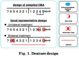
| The following designs were proposed for the unilateral distal extension partial dentures replacing the lower left first and second molars (Fig. 1): 1) Denture with extracoronal magnetic attachment 2) Conventional denture with unilateral design 3) Conventional denture with bilateral design. Bilateral denture design Akers clasp was applied on the distal side of the lower left second premolar, and double Akers clasp was applied on the lower right second premolar and first molar. |
|
 |
|
| 2. Finite element model construction | |
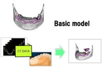
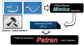
| Each denture design was applied to the FEM model constructed by Ando. The model was fabricated based on the CT data and study model of an actual patient (Fig. 2). The samples for CT scan shown in the fig. 3 were fabricated using scanning resin (Yamahachi dental material) to embed the retainers designed for the present study. Each sample was scanned with Micro CT (Shimazu), and three-dimensional model was constructed using Mimics (Materialize). Morphological data was altered, imported into Patran (MSC), and incorporated into the denture design on the computer (Fig. 3). | |
 |
 |
| Fig. 2. Basis model | Fig. 3. Import of data |
| 3: Analysis model | |
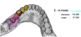
| Each analysis model, element and contact points are shown in Fig. 4. Canine, first and second premolars were interconnected in all models to compare the influence of the difference in denture design on the periodontal tissue and denture movement. | |
| 1) E-A model The model with a bracing arm incorporated into an extracoronal attachment on the lingual side of the lower left second premolar (E-A model) |
 |
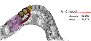
| 2) A-C model The unilateral model with Akers clasps on the mesial side of the left lower first premolar and distal side of the second premolar (A-C model) |
 |
| 3) L-B model Indirect retainer model with a Akers clasp on the distal side of the lower left second premolar and twin clasp on the right lower second premolar and first molar (L-B model) |
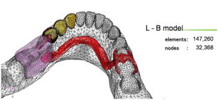 |
| Fig. 4. Analysis models | |
| Analysis | |
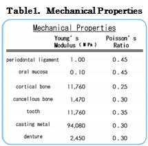
| Mechanical property value was input into the constructed FEM model. The
boundary conditions were applied, followed by the analysis using a nonlinear
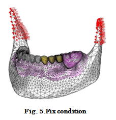
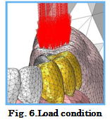
structure analysis solver (Marc2005r3, MSC Software). 1. Analysis condition Contact conditions were applied between a denture and the mucosa, and an abutment and an attachment. The coulomb friction was applied, and friction coefficient was set at μ = 0.01. Analysis type was linear elastic stress analysis, and three-dimensional tetrahedron and pentahedron elements were employed. DELL PRECISION 470 (DELL) was used for the analysis. 2. Components and mechanical properties Table 1 shows model components and mechanical properties of each component. Mechanical property values close to precious metal materials for dental metal ceramic restoration (Degdent Universal, Densply Sankin) that are widely used in clinical practice were applied to the metals used for crown, attachment, and metal frame. For the periodontal membrane and mucosa, exploratory analyses were repeated for the vertical displacement, and mechanical property value close to the reported measurement value was employed. 3. Boundary condition The lower bilateral coronoid processes were under complete restraint (Fig. 5). A total of 10 N loads vertical to the occlusal plane was applied to the occlusal surface of artificial teeth (Fig. 6). |
 |
 |
|
 |
|
| Results | |
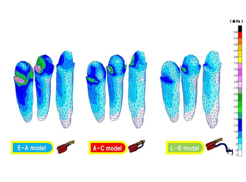
| 1. Stress distribution The following are the results of stress distribution. The Von Mises stress test was used for the stress distribution analysis. 1) Abutment Fig. 7 shows the stress distribution of abutments from the distal-lingual side of the second premolar. The second premolar received the highest stress, followed by the canine and the first premolar. The stress was concentrated on the margin of abutments. Stress concentration was observed around extracoronal attachment and slit in the E-A model with attachments, and just below the rest in the A-C and L-B models with clasps. The stress distribution on the root was measured to assess the stress on the periodontal tissue. The result showed stress concentration on the distal side of the second premolar in all models. The E-A model demonstrated the highest stress concentration, followed by A-C and L-B models. |
|
 |
|
| Fig 7.Abutment | |
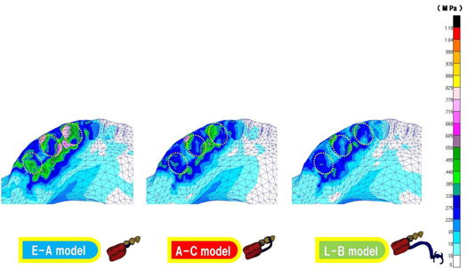
| 2) Alveolar bone Fig. 8 shows the stress distribution of the alveolar bone from the distal-lingual direction. Stress concentration was found around the margin of the alveolar socket especially in the distal side of the canine and mesial side of the first premolar. The E-A model demonstrated the highest stress concentration, followed by A-C and L-B models, suggesting the same trend as the stress concentration on abutments. |
|
 |
|
| Fig 8. Alveolar bone | |
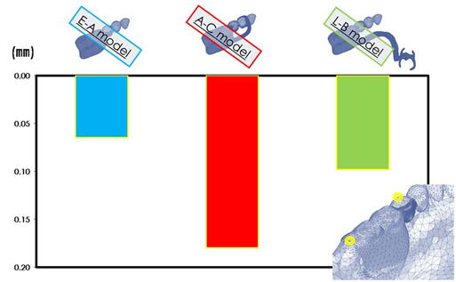
| 2. Displacement 1) Vertical displacement of dentures Fig. 9 shows the vertical displacement of the posterior margin of the denture. The most posterior abutment was used as a reference. Measuring points were the posterior margin of the denture and the cusp tip of the most posterior abutment. The largest vertical displacement was observed in the A-C model. The E-A model showed a smaller vertical displacement than the bilateral L-B model. |
|
 |
|
| Fig. 9. Vertical displacement of dentures | |
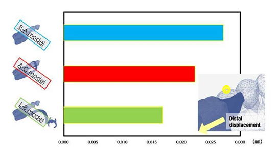
| 2) Distal displacement of abutments Fig. 10 shows the distal displacement of abutments. Measuring point was a cusp tip of the most posterior abutment. The E-A model showed the largest distal displacement of an abutment although the displacement amount was much smaller compared to the vertical displacement. The L-B model showed the smallest distal displacement. |
|
 |
|
| Fig. 10. Distal displacement of abutments | |
| Discussion |
| 1. Analysis model Clasps were fabricated with a scanning resin, and incorporated into the ready-made FEM model. This construction method allows simulation of various denture designs. Three abutments adjacent to the edentulous space were rigidly splinted interconnected in all three models to compare the mechanical properties depending on the denture design. However, rigidly splinting fixed abutments for partial denture supporting abutments is not a common treatment methods. Further research is required to establish clinical evidence. 2. Analysis results The E-A model showed the larger stress distribution on abutments and the alveolar bone compared to the other two models, but showed the smallest vertical displacement. Rigid designs including slit in the attachment, lingual bracing arm and interlocking attachments reinforce the denture. Although this model has the most pleasing aesthetics, the design resulting in large stresses being placed on the remaining tissues. Careful assessment and diagnosis are required prior to selection of this design. The unilateral A-C model is thought to mitigate the patients’ discomfort of patients compare to bilateral partial denture designs. However, the unilateral A-C model demonstrated the largest vertical displacement, suggesting possibility of a poorer prognosis. The bilateral L-B model showed a smaller stress distribution on abutments and the alveolar bone compared to the other two models, and an identical vertical displacement as the E-A model. Considering the small stress distribution on abutments and the alveolar bone and vertical displacement, the L-B model is considered to be the design that provides the most ideal results and possible clinical outcome. |
|
|
| Conclusion |
| Mechanical analysis was performed in three denture designs for the lower left first and second molars loss case, and the following conclusions were drawn.
1. Mechanical properties were different depending on the denture design. It is considered important to design the denture considering patients’ request and periodontal tissue condition.
2. The A-C model demonstrated a larger vertical displacement compare to the E-A model.
3. The L-B model demonstrated a smaller stress on the periodontal tissue compare to the E-A model. This model also showed a small vertical displacement and small abutment displacement, suggesting that the L-B model is the most efficient design.
4. The E-A model demonstrated a small vertical displacement, but a larger stress on the periodontal tissue and abutment displacement compare to the other two models, suggesting that this design is the most rigid among 3 designs.
|
|
|
| References |
| 1. Ando A., Nakamura Y., Kanbara R. and et al: The Effect of Abutment Tooth Connection with Extracoronal Attachment using the Three Dimensional Finite Element Method- Part 2 The Construction of Finite Element Model from CT Data- . JJ Mag Dent 18:2009 2. Tanaka Y.: Dental Magnetic Attachment, Q&A, Ishiyaku Publishiers, Inc(Tokyo),1995 3. Nakamura K., Hiroshi M., Fukuzawa N. and et al: Influence of Heat Treatments on Attractive Force of Magnetic Attachments.J J Mag Dent.6:63-70,1997. |