| #11 Attractive Force Analysis of Magnetic Attachment using Three Dimensional Finite Element Method -Influence of the Keeper Thickness on Attractive Force- |
||
| H. Kumano, T. Masuda, Y. Nakamura, T. Miyata, T. Iwai, T. Kogiso, Y. Ohno, Y. Tanaka | ||
| Removable Prosthodontics, School of Dentistry , Aichi-Gakuin University | ||
| Introduction |
| The clinical efficacies of a magnetic attachment have been widely demonstrated. This includes a small lateral load on an abutment tooth due to its non-mechanical retentive force and aesthetic appearance1). Although the magnetic assembly and retaining keeper are designed to exert a concentrated maximum attractive force within a small particular size and area, the problem of space constrains and attachment positioning related to clinical applications with adjacent or opposing dentition often occurs2,3). It is not recommended to process commercial magnetic attachment since it may diminish attractive force and corrosion resistance. However, partial processing of a keeper is often inevitable to enhance clinical results. In such cases, it is important to understand the influence of processing on the attachment function. |
|
|
| Objective |
| The stainless steel used for magnetic attachments exhibits non-linear attractive force properties. The accounting of non-linear behavior results in difficulties for accurate force calculations. FEM analysis is necessary to estimate the size and structure of a magnetic attachment. The present study focused on the effect of magnetic keeper thickness, and investigated upon the influence of keeper thickness and attractive force using a three-dimensional finite element method. |
| Analysis Methods | |
| 1: Analysis model | |
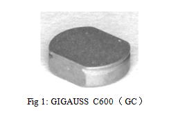
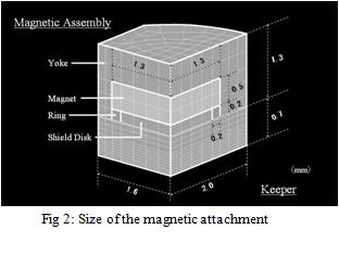
| A common proprietary magnetic attachment was selected as reference model for creation of an analysis model (GIGAUSS C 600 GC) (Fig. 1). Sample measurements were made prior to modeling procedures. Actual and proprietary measurements were compared to estimate the external shape of the attachment. Internal configuration data was also required for modeling but was not available. The sample attachment was embedded, sectioned, and then internally measured to determine internal shape and measurement configurations. An analysis model was constructed using a special software program (MENTAT - MSC Software) and the external and internal attachment measurements. Element breakdown of the analysis area selected was determined to be 10 mm x 10 mm in height and width. A three-dimensional model with ¼ minor axis section in size was constructed considering the axis shape of a GIGAUSS C 600 magnetic attachment. The element type designation was three-dimensional hexahedral element. Element count was 12052, and nodal point was 10395 (Fig. 2). | |
 |
 |
| 2: Analysis condition | |
| The magnet used in the present study was neodymium iron and boron (Nd-Fe-B). The SUS447J1 stainless steel was used for a yoke and a keeper. The magnetic property value was determined based on the thermal property of GIGAUSS D 600 obtained from a data report 4) and manufacturer’s information. Although it was determined that the original stainless steel material of a yoke and keeper was SUSXM27, a different steel substitute value for SUSXM27 required selection. The steel selected for similar and functionally identical magnetic properties was SUS447J1 steel material. The SUS447J1 steel material values were assigned since proprietary information of SUSXM27 was not available. The B-H curve was then approximated and selected from these values, and then, designated as magnetic properties (Table 1). The GiD (CIMNE) was used for the input of the analysis condition, and the MAGNA/FIM (CTC Solution) was used for the analysis. Nastran format was used for the file exchange between MENTAT and GiD. | |
 |
|
| 3: Analysis items | |
| Thirteen items were analyzed when the keeper thickness was changed by 0.05 mm between 0.30 and 0.90 mm. The analysis was performed on the magnetic flux density distributions and attractive forces when the keeper thickness was changed. | |
| Results | |
| 1: Magnetic flux density distribution The comparison of the magnetic flux density distribution with the change of keeper thickness (Fig. 3) showed the specified saturation magnetic flux density distribution between a magnetic and a keeper with 0.90, 0.80, 0.70 and 0.60 mm in thickness. However, no significant difference was confirmed in the magnetic flux density distribution of a magnetic assembly and inner keeper. The area of the specified saturation magnetic flux density distribution increased with a decrease of keeper thickness from 0.50mm to 0.40 mm and 0.30 mm. Oversaturated magnetic flux density distribution was confirmed in the saturated magnetic flux density distribution. The area of the oversaturated magnetic flux density distribution increased with a decrease of keeper thickness. The comparison of the magnetic flux density distribution between major and minor axes in the keeper showed a significant difference in the saturated magnetic flux density distribution in the thinner keeper, and increase in the oversaturated magnetic flux distribution in the long axis. |
|
 |
|
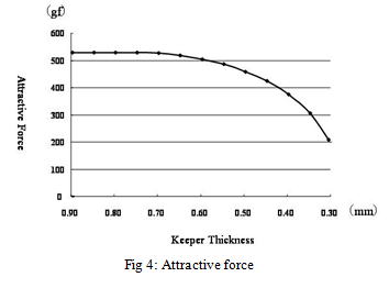
| 2: Attractive force Fig. 4 shows the relationship between a keeper thickness and attractive force. Keepers with > 0.7 mm thickness showed attractive force of 520 – 530 gf. A decrease in the attractive force was observed in keepers with < 0.7 mm thickness. The attractive forces were 95% in 0.6 mm, 86% in 0.5 mm, 71% in 0.4 mm, and 38% in 0.3 mm when the 0.7 mm thickness was defined as 100%. |
|
 |
|
| Discussion |
| The attraction and repulsion force dynamics of a magnet have not been well reported. Although magnetic force and magnetic fields can be measured using specialized measuring devices, it is difficult to design a magnet with maximum magnetic force based solely on the results, and also to verify the optimal properties for minimal field leakage. The FEM technique is the only known method that allows simultaneous visualization of system dynamics under variable conditions. In the present study, we measured the internal structure of a magnetic attachment sample, and constructed the correlated analytical model based on the known measurements. Therefore, the constructed model accurately reproduced the morphology of the original sample. For the analysis condition, a different steel substitute value for SUSXM27 required selection. The steel selected for similar and functionally identical magnetic properties was SUS447J1 steel material. The SUS447J1 steel material values were assigned since proprietary information of SUSXM27 was not available. The B-H curve was approximated, and the magnetic properties were assigned for the magnetic attachment. The further areas of investigation include more accurate measurement and a search for improved magnetic materials. GIGAUSS C 600 was used as a reference in the present study. A significant increase in the saturated magnetic flux density distribution was observed in keepers with <0.7 mm thickness. Attractive force peaked at 530 gf in a 0.7 mm keeper, and gradually decreased with a decrease in the keeper thickness. Ninety percent attractive force was maintained in keepers of >0.55 mm thickness, suggesting that there was no significant decrease in the attractive force. This is considered to be due to the magnetic flux density distribution in the keeper. In a cup-type keeper, magnetic flux density distribution concentrated on the center of minor and major axes of a keeper, and gradually decreased towards the margin. Due to the wide cross-sectional area perpendicular to the magnetic flux, magnetic saturation does not occur with a decrease of the keeper thickness. The influence of saturation magnetic flux density on the attractive force of a cup-type attachment is smaller compared to the sandwich type. Sufficient attractive force for clinical use can be maintained in thin keepers. It is considered that a stainless keeper can be reduced in thickness due to its high saturation magnetic flux density, suggesting further clinical application. |
|
|
| Conclusion |
| The present study focused on a keeper of a magnetic attachment, and investigated the influence of the keeper thickness on attractive force using FEM. The following results were obtained: 1. The area of the oversaturated magnetic flux density distribution increased with a decrease of keeper thickness. Oversaturated magnetic flux density distribution was observed in the saturated magnetic flux density distribution. 2. Attractive force peaked at 530 gf in a 0.7 mm keeper, and gradually decreased with a decrease in the keeper thickness. Ninety percent attractive force was maintained in keepers of >0.55 mm thickness. |
|
|
| References |
| 1. Tanaka,Y.:Dental Magnetic Attachment,Q&A,Ishiyaku Publishers,Inc(Tokyo),1995 2. Nakamura,Y.:Stress analysis of overlay denture and a magnetic attachment using finite element method. J Jpn Prosthodont Soc, 42:234-245,1998 3. Nakamura,Y.Tanaka,Y.Ishida,T.and et al:Dynamic Analysis of a Magnetic Attachment using Finite Element Method –Comparison of the two dimensional analysis with the three dimensional one-.J J Mag Dent.8:57-62,1999 4. Miyata,T.Niimi,J.Ando,A.and et al: Influence of heating of a magnetic attachment on the attractive force. J J Mag Dent.17:44-50,2008 |