| #3 Influence of the Measuring Methods on the Attractive Force of Magnetic Attachments |
||
| Y. Nakamura, K. Shoji, R. Kanbara, H. Kumano, A. Ando, T. Iwai, T. Kogiso, Y. Ohno, Y. Tanaka | ||
| Removable Prosthodontics, School of Dentistry, Aichi-Gakuin University | ||
| Introduction |
| As handing of a removable denture, most of dentists usually instruct
a patient that a denture should be removed overnight. However, on patients
with bruxism, dentures are recommended to wear for protecting teeth occasionally. Meanwhile,
in spite of proposing to use dentures while asleep, bruxism may be caused
inThere has been an increasing use of magnets in the clinical dental setting.
Magnetic attachments are excellent retaining devices with many functional
applications and aesthetic benefits. These attachments have also had high
satisfaction ratings for the treatment results when used in conjunction
with dental implant treatments. A magnetic attachment consists of a magnetic
assembly and a keeper. The optimum attractive force relationships between
these two components are of prime importance. Therefore, a careful evaluation
of the relationship of attractive force and magnetic assembly mechanism
is required. Our department has been conducting studies on magnetic attachments
such as attractive force measurements to elucidate magnetic attachment
properties. Several different methods have been reported on magnetic attachment
measurement techniques. A specialized jig orientation measuring device
was designed, reported and tested upon at Department of Removable Prosthodontics,
School of Dentistry, Aichi Gakuin University. The validity of the attractive
force measuring method using this jig was confirmed.
|
| Objectives |
| A simply designed device for the measurement of the attractive force between a magnet and a keeper was proposed by the Australian magnet research institute at the 2009 ISO conference. The comparison to existing measurement techniques was desired. In the present study, we compared the results of the attractive force measurement method proposed by Australian magnetic institute with our measurement method to verify the validity of the newly proposed method. |
| Materials and methods | |||||||||||||||||||||||||||||||||||||||||||||
| 1.Materials | |||||||||||||||||||||||||||||||||||||||||||||
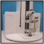
| GIGAUSS C (GC) was used as a magnetic assembly testing subject(Fig. 1). Attractive force was measured using a compact tabletop EZ-test tensile tester (Shimazu) (Fig. 2). | 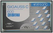 |
 |
|||||||||||||||||||||||||||||||||||||||||||
| Fig 1: GIGAUSU C600 (GC) | Fig 2: EZ test (SIMAZU) | ||||||||||||||||||||||||||||||||||||||||||||
| 2.Methods | |||||||||||||||||||||||||||||||||||||||||||||
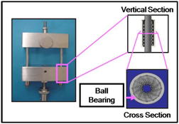
| 1) Experimental items (1) Attractive force measurement using a special jig
|
|||||||||||||||||||||||||||||||||||||||||||||
 |
 |
||||||||||||||||||||||||||||||||||||||||||||
| Fig 3: special jigu | Fig 4: mold and a guide bar | ||||||||||||||||||||||||||||||||||||||||||||
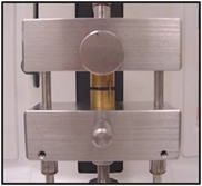
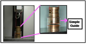
(2) Attractive force measurement proposed by the Australian magnetic institute.
|
|||||||||||||||||||||||||||||||||||||||||||||
 |
|||||||||||||||||||||||||||||||||||||||||||||
| Fig 5: simple jig based on the Australian design proposal | |||||||||||||||||||||||||||||||||||||||||||||
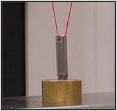
(3) Attractive force measurement without vertical and horizontal restrictions
|
|||||||||||||||||||||||||||||||||||||||||||||
 |
|||||||||||||||||||||||||||||||||||||||||||||
| Fig 6: attractive force measurement without vertical and horizontal restrictions | |||||||||||||||||||||||||||||||||||||||||||||
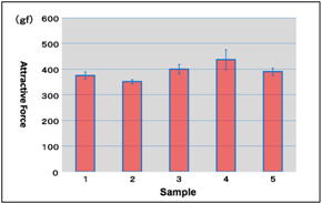
| 2) Measurement conditions Attractive force measurement was repeated 10 times for each of the 5 samples using the EZ test. The cross head speed was 5 mm/minutes. |
|||||||||||||||||||||||||||||||||||||||||||||
|
|
|||||||||||||||||||||||||||||||||||||||||||||
| Results | |||||||||||||||||||||||||||||||||||||||||||||
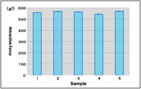
| 1. Attractive force measurement method using a special jig | |||||||||||||||||||||||||||||||||||||||||||||
|
|||||||||||||||||||||||||||||||||||||||||||||
| Discussions |
| 1. The design of the simple guide in the measuring method proposed by
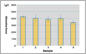
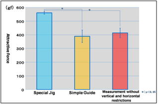
the Australian magnetic institute We fabricated a simple guide based upon a design presented by the Australian magnetic institute. However, exact duplication was unknown since there was no specific information regarding guide design. One application method considered direct application of a keeper and a magnetic assembly attractive surfaces. However, frictional resistance during the traction would likely adversely affect accurate measurement. Correct guide placement was repeatedly difficult as the combination of a keeper and a magnetic assembly were only 2 mm in thickness. Recommendations and considerations for the optimal measurements of magnetic attachments include indirect guides for placement positioning when using the special jig testing apparatus reported. In the present study, measurements were performed by using a mold in a magnetic assembly and a keeper, and a guide was placed indirectly to the mold. This design seeks to minimize the friction resistance between a mold and a guide. Inter-guide lubricans were considered but were not used. The effect of added lubricants could not be accurately assessed. 2. Measurements A significant difference was observed in the obtained attractive force methods using a simple guide and another method without vertical and horizontal restrictions compared with the special jig method. The method using a special jig showed the highest attractive force measurement values for the identical magnetic device. 1) Measuring method of the attractive force using a special jig Greatest measurement accuracy was achieved by using the special jig design testing method. Unlike other measuring methods, there was vertical and horizontal axis control of the magnetic attachments during separation. Friction resistance during traction was not encountered due to the ball bearing structure design and minimal measurement error. Disadvantages of the special jig design remain including high cost and high maintenance requirements. Considered of these issues lead to a simple measuring method. The jig design is of importance for accurate measurement of magnetic assembly attractive forces. The present study demonstrated the role of a special jig in the attractive force measurement, and confirmed the measurement accuracy. 2) Attractive force measurement proposed by Australian magnetic institute (Simple guide) The results of the attractive force measurement using a simple guide showed lower magnetic force measurements. This finding is thought to be due to the lack of vertical control during the traction of a magnet assembly. The traction using a cotton string produces not only vertical but also horizontal stress between a magnetic assembly and a keeper in the guide, causing a non-axial rotational force. This force creates rotational movement when a magnetic assembly and a keeper detatch, resulting in a decrease in measureable attractive force. 3) Attractive force measurement without vertical and horizontal control A decrease in the attractive force was observed due to the rotational movement caused by traction with a cotton string. The results of the attractive force measurement without vertical and horizontal control showed similar measurement values as the degree of attractive force in the simple guide method (Fig 10). The results suggested that the rotational force caused by cotton string traction affects the results of the attractive force measurement more than the horizontal restriction design. |
| Conclusions |
| The influence of the measuring methods on the attractive force of magnetic attachments was investigated. Our prior report described the attractive force measurement of a magnetic assembly using a special jig, but a more simple method was proposed by Australian magnetic institute. In the present study, the attractive force of magnetic attachments using a simple guide was measured according to the specific designs proposed by the Australian magnetic institute, and the results were compared. The following conclusions were drawn: 1. The measurement error was the smallest in the measuring method using a special jig that controls vertical and horizontal direction during traction, and the highest attractive force was measured. 2. Although attractive force measurement using a simple guide fabricated according to the proposal appears to provide horizontal displacement. The effectiveness of this design component was not shown. |
| References |
| 1. Tanaka,Y.: Dental Magnetic Attachment,Q&A,Ishiyaku Publishers,Inc.(Tokyo),1995. 2. Gillings,B.R.D.: Magnetic retention for complete and partial overdentures, Part.J.Prosthet.Dent.,45(5):484-491,1981. 3. Jackson,T.R.: The application of rare earth magnetic retention toosseointegrated implant.Inc.J.Oral & Maxill.Imp.,1:81-92,1986. |