14. Development of
a Measurement System for Jaw Movement
N. Ishihara, M. Akutagawa1 and Y. Kinouchi1
Graduate School of
Advanced Technology and Science, The Univ. of Tokushima
1Institute of
Technology and Science, The Univ. of Tokushima
Introduction
The number of people who are suffering from temporomandibular arthrosis are increasing. It is one of the fundamental factors to know the jaw movement in diagnosing it. However to measure the jaw movement is one of the most difficult measurement because a measurement system requires high precision acquisition of six degrees of freedom. In addition, measured points are invisible because they are hidden by the skin. So, few of them are satisfying so far.
We try to measure the
jaw movement by using a small magnet, 18 three-dimensional magnetic sensors (MI
sensors) and the Neural Networks (NN). The small magnet is attached at the jaw
in the measurement area, and 18 MI sensors arranged around the magnet measure
the magnetic flux density. Outputs obtained from MI sensors are presented to
the NN. And the position and direction of the magnet are estimated. This
experiment has been conducted by a computer simulation. According to results of
the computer simulation, estimation errors are up to 10 μm and 0.002 degrees.
In this study, a measurement system that adapts to the computer simulation was developed. In the measurement area, the magnet is put and the outputs of the MI sensors are obtained. And they are presented to NN. The position and direction of the magnet are estimated.
Objective
The purpose of this study is to develop an experimental measurement system for jaw movement and confirm its applicability.
Materials and
Methods
We developed a device to estimate the position and direction of the small magnet. Figure 1 shows the MI sensor and Figure 2 shows the device that we developed. In this study, 18 MI sensors are used as shown Figure 3 (a), (b) and (c). The direction of the magnet is restricted within 60°as shown in Figure 3 (c).
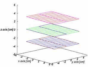
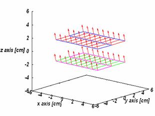
As shown in Figure 4
(a), the small magnet is put in the measurement area (100mm x 100mm x 100mm)
with the direction of the magnetic axis turned to z axis. The magnet is on the
grid point. On the plane, each grid point is away by 10mm in x axis, by 30mm in
y axis and by 30mm in z axis. The output value of 18 MI sensors of 33 points is
acquired each plane. These data is input to the NN. And coordinates (![]() ) and the direction (
) and the direction (![]() ) of the magnet are output.
) of the magnet are output.
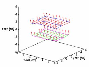
Next, as shown in Figure 4(b), the small magnet is put in the measurement area with the direction of the magnetic axis inclined 15°(the direction of arrows). Each grid point is away by 10mm in x axis, by 30mm away in y axis and by 30mm in z axis.
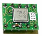

Fig.1: three-dimensional magnetic sensor AMI501
Aichi Micro Intelligent Corporation

Fig.2: The experiment device
100

(c) (d)
Fig.3: Measurement area and the position of sensors
(a) (b)
Fig.4: position and direction of the magnet
Results
Figure 5(a) shows the output of the NN when the magnet put like Figure 4(a), and Figure 5(b) shows the output of the NN when the magnet is put like Figure 4(b). Those results of the error are shown in Table1.
Table 1 estimated error of the position and direction
|
case |
Position error [mm] |
Direction error [deg.] |
||
|
Average |
Maximum |
Average |
Maximum |
|
|
(a) |
3.82 |
13.43 |
3.20 |
7.71 |
|
(b) |
4.67 |
11.47 |
4.08 |
6.36 |
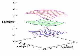

(a) (b)
Fig. 5: output of the NN
In our measurement system, the position and the direction of the magnet were estimated by the error margin of about 4.5mm and 4.0°.
Conclusions
We confirmed the proposed
measurement system is available to measure the movement of a magnet. However, in
this stage, accuracy of the measurement is not enough to apply practical
diagnoses.
References
1. Xu XHANG Measurement System of Jaw Movement by Using BP Neural Networks Method and a Nonlinear Least-Squares Method: IEICE TRANS. INF., VOL.E85-D,NO.12 DECEMBER 2002