5. Effects of Dental Alloys and Magnetic Keeper on MRI.
Part2 Relationship between Cast Crowns and Artifacts of Axial Plane Images
Graduate School, Tokyo Medical and Dental University Section of Removable Prosthodontics
Introduction
Various kinds of metal alloy have being applied to dental treatment, for example, orthodontic wires, claps, inlays, crowns, denture frames, implant and so on depending of their adequate properties. In addition, magnetic attachments (MA) are developed and used as the retainers of conventional or implant-supported overdentures. Since 1990's, MA has been becoming popular in Japan while even it is not so well known in Europe and USA. Nevertheless, with the magnetic field of Magnetic Resonance Images loss of signal occurred in the head and neck region by the used of dental alloys. In order to compare their signal intensity generated, crowns of different dental alloys and pre-fabricated magnetic keeper were used and the distribution of their signal intensity will be compared at the same distance.
Objective
MRI artifacts, generated by dental alloys caused some problems according to their magnetic characteristics depending on whether they are diamagnetic, ferromagnetic or paramagnetic substances. The aim of this study was to examine the artifacts area around the specimens by analyzing MRI dicom data with comparing the Coefficient variance (CV) values of signal intensity among dental alloys.
Materials and Methods
1. Samples
Four clinical dental alloys and one pre-fabricated magnetic keeper were selected (Table1). The formers were cast into a similar lower first molar using a same shell crown (Mesio-distal: 8 mm; bucco-lingual:7.5 mm). Identically shaped acrylic resin crown was used as a control. 5 samples for each material (total of 20 crown shapes and 5 magnetic keepers) were investigated (Fig. 1).
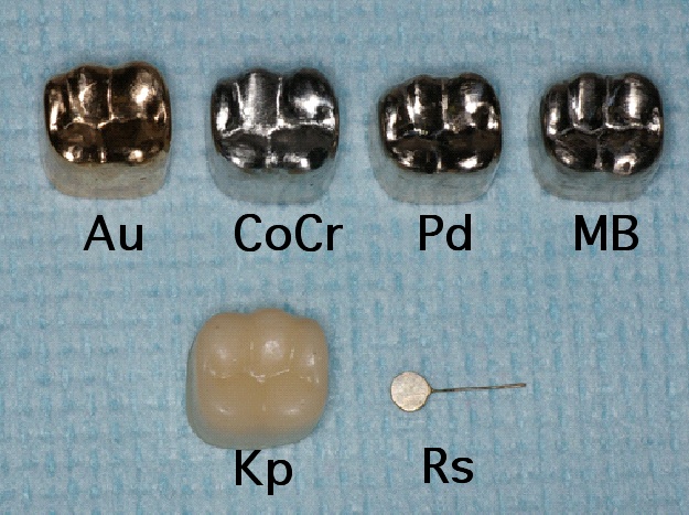
Fig. 1 Samples
Table 1
2. Phantom and Agar
A cubic phantom (Fig. 2) was used. To fix the sample in the phantom, a reversible hydrocolloid, agar was used. The agar was first melted using a Colloid Bath ST-600 (Sankin Corp. Tokyo, Japan) at 80 degrees C for 120 minutes. The agar was then poured until the half of the cubic phantom, about 70 mm from the base. After the agar had gelled, the sample was placed in the middle of the phantom. Finally a second layer of agar was then poured to entirely fill the phantom (Fig. 2).
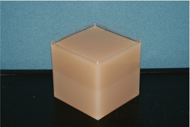
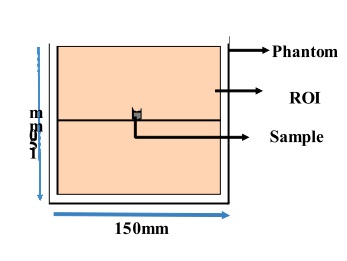
Fig. 2 Cubic Phantom (150mm×150mm×150mm)
3. MR Imaging
The phantom was placed in a head and neck coil on the table of a 1.5-Tesla MRI apparatus (Fig. 3) (Magnetom Vision, Siemens, Germany). To investigate a sequence of artifacts images in the axial, coronal and sagittal planes, a T1-weighted spin-echo sequence (550 msec/14 msec, repetition time TR /echo time TE) and T2-weighted turbo spin-echo sequence (3400msec/90msec TR/TE) were used with an acquisition time (TA) of 03:33. All images were taken with the following parameters: Number of acquisitions (AC), 3; Number of Slices, 19; Thickness, 5-mm; Pixel size, 0.9 mm x 0.9mm; Matrix size, 256 x 256. FOV, 230/mm; Scan time, 6 min 10 sec; .
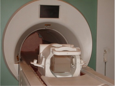
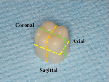
Fig. 3 MRI apparatus table and Axial, Coronal, Sagittal planes
4. Data and Stastical Analysis
The Digital Imaging and Communications in Medicine (DICOM) data from MR images of each sample were analyzed with Image J software (Bethesda, Maryland, USA) and a region of interest (ROI) was drawn around square images for data acquisition. The mean and standard deviation (SD) of signal intensity (SI) were obtained from the pixels within ROI images and the mean coefficient of variation (CV) for each sample was calculated and evaluated with one-way ANOVA and Dunnett's test. P<0.05 was considered significant.
Results
1. Artifacts in MR Images
Artifacts from the center (0 mm) are shown in axial T1-WI images. With Au, MB and Pd, artifacts appeared as a black gap. With Kp and CoCr, a white area was observed. In the Rs image, the crown's shape can be seen clearly. (Fig. 4)
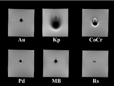
Fig. 4 Axial T1-WI MRI images from the center of the sample. Artifacts in the ROI.
2. SI and Pixel Numbers
Judging from the histograms, the SI for Kp and CoCr are widely distributed. The histograms for Au, MB and Pd showed a narrow SI distribution. (Fig. 5)
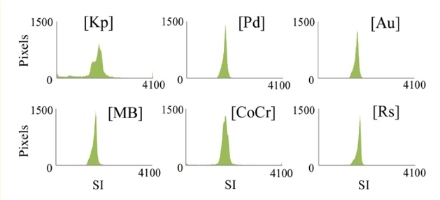
Fig. 5 Histogram from axial T1 - WI
3. Coefficient of Variance
As for CoCr, in coronal, the CV of SI was significantly different up to 40 mm, but with a gap of non-signal from 15 to 30 mm..
As for Kp, the CV was significantly different in axial T1-WI up to 70 mm, until the edge of the ROI.
As for MB, in coronal, a significant difference in SI was seen up to 5mm.
As for Pd and Au, Compared to Rs at 0 mm, Au and Pd did not show any significant difference in any of the coordinate planes. (Table 2)
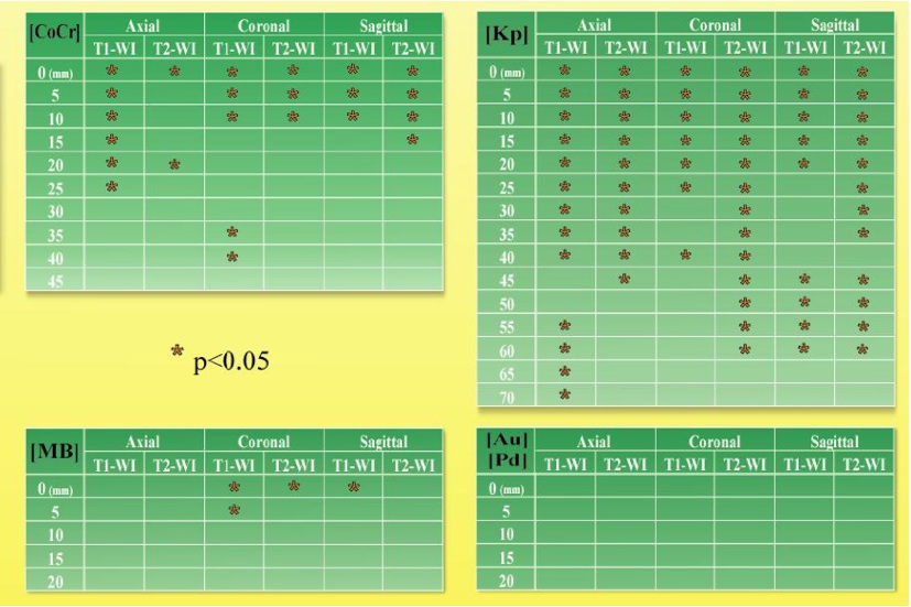
Table 2 Comparison of Rs to dental alloys
Discussions
Dental alloys are often used in prosthodontics dentistry more than resin for their properties as higher life expectancy, maintenance of good condition.
Au, MB, CoCr and Pd are widely used for fixed prostheses in dental clinics. In addition, magnetic attachment had been proved to be a concrete solution to eliminate the lateral force to the abutment and the manipulation of the denture is easy even by handicapped patients.
Nevertheless, to avoid the artifacts area, the dental keeper can also be removed from the oral cavity. As it is situated in the mouth, it is not a disturbance in the other part of the body that needs to be exposed to MRI. Compared with Au, MB Pd and CoCr, Kp showed significant difference until 20 mm.
Conclusions
Compare to Kp and CoCr, artifacts generated by Au, MB and Pd alloys were less than the one generated by keeper from 0 to 20mm.
Mean SI per pixel for Kp in axial images was significant with all the samples.
CoCr showed significant difference with all the specimens in T1 WI from 0mm to 20mm. In T2 WI, no significant difference was registered for CoCr with Au, Pd, MB except with Rs at 0mm T2 WI.
Coefficient of variation of the signal intensity might be a practical way to calculate the artifact generated by metallic abutments.
References
1. Shafiei F, Honda E, Takahashi H, et al. Artifacts from dental casting alloys in magnetic resonance imaging. J Dent Res 82: 602-606, 2003.
2. Shellock FG, Kanal E. Aneurysm Clips. Evaluation of MR imaging artifacts at 1.5T. Radiology 209: 563-566, 1998.