Foreign Dental Magnetic Attachments
1Department of Removable Prosthodontics, Tsurumi University School of Dental Medicine
2Division of Dental Biomaterials, Tohoku University Graduate School of Dentistry
3The First Department of Prosthodontics, School of Dentistry , Aichi-Gakuin University
4Department of Partial Denture Prosthodontics, Nihon University School of Dentistry
5Hitachi Metals Co., Ltd.
6Department of Electrical and Electronic Engineering Faculty of Engineering, The Univ. of Tokushima
7Graduate School, Tokyo Medical and Dental University Section of Removable Prosthodontics
Introduction
Our research team has tried to standardize internationally dental magnetic attachments used in the world. This study was fully supported by the NEDO Grant (05IS051) aiming at "Development and Standardization of the Dental Magnetic Attachment".
Objective
The following items concerning the foreign dental magnetic attachments were examined;
1. Characteristics
2. Internal structures and materials
3. Attractive force measurements and cyclic load testing
4. Influence of keeper tilt angle on retentive force
5. The leakage magnetic fields
1. Characteristics
Department of Removable Prosthodontics, Tsurumi University School of Dental Medicine
Objective
Large numbers of dental magnetic attachments of domestic origin are used in Japanese dental practice; however, little is known about foreign-made ones. Thus, seven types of commercially available magnetic attachments in the foreign market were investigated. The purpose of this report is to describe the characteristics of each attachment, namely, its appearance, purpose, and fixation methods to an implant or root.
Materials and Methods
Seven types of magnetic attachment systems compatible with dental and craniofacial implants/abutments or teeth/roots were selected for this report. The product name, manufacturer, and country of origin of each attachment are listed in Table I. The purpose and fixing methods of each were investigated using the respective brochure and manufacturersf instructions. Although the keeper included a magnet in several of the attachment systems examined, all components fixed to an implant or root are called a keeper in this report.
![[Table.1]](image001.jpg)
Results and Discussion
Figure 1 shows photographs of assembled keepers and magnets on paper ruled into 1-millimeter squares. The use of each attachment and the fixing method for the keeper and magnets are indicated in Table II. Five of seven attachments were manufactured in Europe (Netherlands: 1, Germany: 2, England: 2), and the others, in the USA. Although four attachments (Dyna magnet, Titanmagnetics, Magnedisc, and Shiner smart magnet system) are used for both root and implants, two attachments (Micro plant magnet and Maxi magnet) are only for implant use. As a specialized use, the Multi-purpose magnet is used for sectional dentures and obturators. Keepers are generally cemented in cast root coping or directly bonded to the tooth/root. Alternatively, root coping is cast with a magnetic alloy (Dyna Alloy) or using the cast-on technique for Magnedisc. For implants, all keepers are placed on the implant by screw fixation.
![[Fig.1]](image002.jpg)
![[Table.2]](image003.jpg)
Conclusions
These attachments are used as retainers for overdentures and maxillofacial prostheses. Foreign magnetic attachments are comparatively larger than Japanese ones, have an open magnetic circuit, and are commonly used for implant overdentures.
2. Internal structures and materials
Division of Dental Biomaterials,Tohoku University Graduate School of Dentistry
Introduction
Domestic dental magnetic attachments have developed as a retainer for prosthetic appliances, which utilizes magnetic attractive force, and many Japanese researchers and dentists also have studied internal structures and materials used to make the domestic magnetic attachments. Recently, foreign-made dental magnetic attachments have arrived on the market. However, very few of Japanese researchers are familiar with them, and their internal structures and materials are still unknown.
Objective
Objective of this study is to investigate the internal structures and materials used to make some available foreign-made dental magnetic attachments.
Materials and Methods
1.Magnetic attachments
The foreign-made dental magnetic attachments such as Dyna WR Magnet (Dyna Dental Engineering, Netherlands),Titanmagnetics System (Steco system technic, Germany), MICROPLANT (Gebr. Brasseler GmbH, Germany), Maxi Magnet (Technovent, UK), Magnedisc 800 (ATTACHIMENTS INTERNATIONAL, USA), and SMART KIT (Preat Corporation, USA) were examined.
2.Methods
Centers of the magnetic assemblies and keepers were cut vertically using a diamond cutter, and their cross section surfaces were observed to investigate the internal structures. The materials used to make the magnetic assemblies and keepers were also analyzed qualitatively and quantitatively using an electron probe micro-analyzer (EPMA, JXA 8900, JEOL, Japan).
Results
Figure 1 shows the cross section surfaces of the magnetic attachments. Most magnetic assemblies have the structure that a Nd-Fe type magnet core was sealed closely with a titanium or Ti-6Al-4V alloy cover. The keepers, which are to screw in the fixtures of dental implants, can be called the second magnetic assemblies rather than keepers because they also had the same structure. Although domestic dental magnetic attachments usually utilize the attractive force between a magnet core and a keeper made of the magnetic stainless steel, these foreign magnetic attachments utilized the attractive force between magnet cores buried in a set of magnetic assemblies.
![[Fig.1]](image004.jpg)
On the other hand, there are the universal type keepers made of magnetic stainless steels in the case of Maxi Magnet (447J1), Magnedisc 800 (444), and Smart Kit (630). In special, the keeper of Maxi Magnet is composed of a disk of 447J1 buried in a titanium root cap.
Figure 2 shows the composition image and the element distributions on the cross section surface of Magnedisc 800. Closed circuits of the sandwich type and the cup yoke type magnetic assemblies are found in the magnetic assemblies such as Maxi Magnet and Magnedisc 800, respectively.
![[Fig.2]](image005.jpg)
Fig.2 Composition image and element distributions on the cross section surface of Magnedisc 800
The internal structures and materials used to make the available foreign-made dental magnetic attachments were summarized in Table 1. The foreign-made dental magnetic attachments have excellent corrosion resistance because most of their external covers were made of titanium or titanium alloy. However, titanium and magnetic stainless steels are likely to contact each other in the case of universal type keepers made of the magnetic stainless steels, when they are screwed to the fixture of dental implants.
It is expected that the foreign-made dental magnetic attachments possibly released more leakage flux than domestic ones do because the second magnetic assembly as a keeper with an open magnetic circuit is set in the oral cavities.
Table 1 The internal structures and materials used to make the foreign-made dental magnetic attachments
![[Table.1]](image006.jpg)
Conclusions
Most of the foreign-made dental magnetic attachments are sealed with external covers made of titanium or titanium alloy, and employ open circuits with respect to the magnetic circuit. On the whole, we receive the impression that their sizes are much larger than those of domestic ones.
3. Attractive force measurements and cyclic load testing
The First Department of Prosthodontics, School of Dentistry, Aichi-Gakuin University
Introduction
Magnetic attachment of different manufacture, may offer differences in physical property and quality including greater stability and retention, ease of manipulation, superior esthetic applications, and reduction of stress to abutment teeth in the various clinical settings shown through research and development. There are several magnetic attachments available on the foreign market. However, since many of these products are available only through commercial means, development process and proprietary details of design and specifications are not readily available in academic journals, and thus even accurate development time remains unknown.
Objective
In this preliminary study on seven foreign-made magnetic attachments that were obtained and compared to the GC GIGAUSS. We measured attractive force of magnetic attachments, and investigated the change in surface morphology of keepers after applying cyclic loads to measure the mechanical strength of keepers.
Materials and Methods
Attractive force was measured by a table-top material tester (EZ Test) using a customized JIG and die device. Measurement conditions were as follows; Crosshead speed: 5mm/min, number of samples: 6 samples of each kind, number of measurement: 10 times (Fig.1 ).
Subsequently, cyclic loading testing was performed to measure the mechanical strength of keepers. The susXM27 stainless steel bar was used to apply cyclic loads (Fig. 2).
![[Fig.1 2 3]](image007.jpg)
We conducted surface observation, strain measurement, and attractive force measurement after applying cyclic loads on samples. A stereoscopic microscope was used for the surface observation. The shape of keepers was measured with three-dimensional digitizer for the strain measurement (Fig. 3).
The digital data obtained was modeled using three-dimensional CAD system, and strain was measured on this model. Attractive force measurement followed the same procedure as used in the preliminary study.
Results
(1) Preliminary study before the tapping test
Fig. 4 shows a comparison of attractive force between our measurement results and values provided by manufacturers. Our measurement value was lower by 10-20% compared with values provided by manufacturers.
![[Fig.4]](image008.jpg)
Fig. 5 shows a comparison of attractive force per unit adsorption area.
![[Fig.5 6]](image009.jpg)
Foreign-made magnetic attachments showed attractive force less than half of Japanese GIGAUSS D600.
Fig. 6 shows the attractive force per unit volume.
The results showed significantly low attractive forces in foreign-made magnetic attachments except MAGNEDISC 800 (US) compared to GIGAUSS D800. This is considered to be due to the differences in the magnetic properties and magnetic circuit.
(2)After the tapping test
Fig. 7 shows the surface texture of keepers before and after applying cyclic loads in each magnetic attachment (Left: before loading, Right: after loading). Each of four magnetic attachments showed a loss of surface gloss, scratches overall, and stretched parts in the margins.
The following four magnetic attachments showed the similar results. However, in the Smart Magnet Kit, marginal region of a keeper was found flat. This is because a beater bar kept pounding the protruded marginal region (Fig. 8).
![[Fig.7 8]](image010.jpg)
Fig. 9 shows the results of the strain test. DYNA demonstrated the smallest strain of 0.007 mm. An outward bulge was observed in MicroPlant.
Marginal strains were observed in the following four types of magnetic attachments. Outwards bulges were also observed in SmartKit and Maximagnet (Fig. 10).
![[Fig.9 10]](image011.jpg)
Fig. 11 shows the results of attractive force measurement. Little decrease in the attractive force was observed in DYNA, Titanium Magnetix, GIGAUSS D600. Multi-purpose MAGNET SYSTEM, Magnedisc, Maximagnet demonstrated moderate decrease.
MicroPlant and Maximagnet demonstrated significant decrease due to their unique figures.
![[Fig.11]](image012.jpg)
Conclusions
Although some of the large size foreign-made magnetic attachments that we used in this study showed the same level of attractive force as domestic magnetic attachments, attractive force per unit area/volume was extremely small, suggesting a lack of high performace of attachments.
Several samples demonstrated fine scratch on the surface and deformation at the margin of a keeper after the tapping test. All seven samples showed a decrease in the attractive force after load application, but no significant decrease in the attractive force was observed in GIGAUSS.
4. Influence of keeper tilt angle on retentive force
Department of Partial Denture Prosthodontics,Nihon University School of Dentistry
Conclusions
The magnetic attachment shows maximum retentive force when the direction of detachment is perpendicular to the joint surface of the keeper and the assembly1). Further, the keeper is placed parallel to the occlusal plane of the overdenture, and the prosthesis is supported against the occlusal force. However, an anterior tooth is tilted in a direction perpendicular to the occlusal plane and has a possible harmful influence on the occlusal force when the keeper is placed parallel to the occlusal plane. (Fig. 1)
![[Fig.1]](image013.jpg)
Orthogonalizing the keeper surface in the direction of the vertical to the axis of the anterior root of the overdenture is recommended; however, there are few studies on the retentive force of the inclined magnetic attachment.2)
Objective
The purpose of this study was to evaluate the retentive force of the magnetic attachment at various keeper angles of the overseas magnetic attachment.
Materials and Methods
1. Magnetic attachment
The magnetic attachment that was tested consisted of a magnetic assembly and KB keeper of Gigauss C600 (GC, Japan), Magnedisc 800 (Attachments International, USA), Titanmagnetics (Steco System Technic, Germany), Dyna Wear Resistant Magnet (Dyna Dental Engineering, Netherlands), Maxi Magnet (Technovent, UK), Multipurpose Magnet System (Technovent, UK), and Microplant (Gebr. Brasseler GmbH, Germany). Six specimens of magnetic attachments are subjected to the test (n=6).
2. Tensile test
A rectangular parallelepiped (15 ~ 15 ~ 30 mm) column was prepared by using acrylic resin. The acrylic resin rectangular column was cut at the center at angle of 0, 45 and 90. (Fig. 2)
![[Fig.2]](image014.jpg)
Magnetic assemblies and keepers are attached to rectangular column using Cyanoacrylate. The retentive force of the magnetic attachment was investigated using the testing jig and measured by universal testing machine (EZ-TEST, Shimadzu, Japan) at 5 mm/min of cross head speed . (Fig. 3,4) This testing jig contains linear ball slide to prevent sidewise movements of the specimen.
![[Fig.3 4]](image015.jpg)
Results
Retentive force
Fig. 5 shows the retentive force at various keeper angles. The retentive force of Gigauss C600 was 5.6 N at 0, 3.7 N at 45 and 0.7 N at 90, Magnedisc 800 was 6.6 N at 0, 4.8 N at 45 and 1.4 N at 90, Titanmagnetics was 3.1 N at 0, 2.2 N at 45 and N/A at 90, Dyna Wear Resistant Magnet was 2.6 N at 0, 1.9 N at 45 and 0.7 N at 90, Maxi Magnet was 6.3 N at 0, 4.4 N at 45 and N/A at 90, Multipurpose Magnet System was 6.4 N at 0, N/A at 45 at 90, Microplant was 0.8 N at 0, N/A at 45 and 90.
![[Fig.5]](image016.jpg)
Discussions
For reasons of marginal shape of keeper and magnetic assembly, Titanmagnetics, Maxi Magnet, Multipurpose Magnet System and Microplant are not available for the test at the 45 or 90 of keeper angle. With increasing keeper angle, retentive force of each magnetic attachment systems is decreased similarly. It may be thought that the retentive force observed in this investigation was the result of shear and tensile forces.
The retentive force is reduced at an increased keeper angle, and the occlusal force is directed to the root direction.
Assessment of the abutment teeth is required to reduce the keeper angle to the occlusal plane.
Conclusions
1. The retentive force of magnetic attachments reduced with increase in the setting angle of magnetic attachment.
2. Tensile test was not available for some overseas magnet at the keeper angles of 45 and 90.
3. In this study, the experimental testing jig was useful in reducing the slippage of the magnetic attachment.
Acknowledgment
This study was supported by the NEDO Grant (05IS1, 2005) and the Sato fund.
References
1)Umekawa Y, Kokubu M, Nagai E, Ohtani K, Fujimoto T, Katakura Y, Takamura M, Sakaguchi S, Ishigami T, Influence of keeper tilt angle on retentive force of magnetic attachment, J J Mag Dent 16:10-13, 2007.
2) Nakamura Y, Stress analysis of an overlay denture and a magnetic attachment using finite element method, J Jpn Prosthodont Soc 42(2):234-245, 1998. (in Japanese)
5. The leakage magnetic fields
Hitachi Metals Co., Ltd.
*Department of Electrical and Electronic Engineering Faculty of Engineering,The Univ. of Tokushima
Objective
Objective of this research is the measurement and the evaluation of the leakage magnetic fields strength of the dental magnetic attachments made in Japan and overseas.
Materials and Methods
1. Equipments
To measure the leakage magnetic fields of the dental magnetic attachments, the gauss meter (F.W.Bell Model 9500) and the hall element prove (F.W.Bell Model HTM95-0608) were used.
2. Measurement
2.1 Pairs of the magnet assembly and the keeper
The leakage magnetic field was measured at the condition that the magnet assembly and the keeper are attracted.
The magnetic field strength were measured at the each positions of around the magnetic dental attachments for each direction of the x-axis and the z-axis (Fig. 1) and the leakage magnetic field strength were calculated as the composed magnetic field strength of those values.
The leakage magnetic field strength were plotted to evaluate and to compare the conditions of each magnetic dental attachments (Fig. 2).
![[Fig.1 2]](image017.jpg)
2.2 The magnet assembly
The leakage magnetic fields of the magnet assemblies at the distance of 2.3mm from the surface of the magnet assemblies were measured.
The measurement method was same as 2.1.
Results
1. Pairs of the magnet assembly and the keeper.
Table 1 shows the leakage magnetic fields strength at the condition of the magnet assemblies and the keepers were attracted.
![[Table. 1]](image018.jpg)
Almost of the samples showed the lower leakage magnetic fields strength than 40mT, the guideline of static magnetic field strength indicated by W.H.O in 2007. Magnedisc 800 and Phisio Magnet #35 showed low values specially.
2. The magnet assemblies
Table 2 shows the leakage magnetic fields strength of the magnet assemblies.
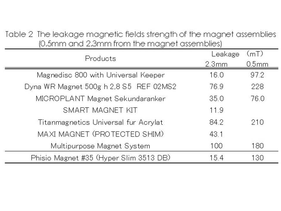
The leakage magnetic fields strength of the magnet assemblies at 0.5 mm from the magnet assemblies showed higher values than the W.H.O guideline. On the other hand, some of them showed the lower values than the W.H.O. guideline at 2.3mm from the magnet assemblies. It seems that the difference of the magnetic circuits of each dental magnetic attachment is the cause of these values.
Discussions
Usually the magnetic dental attachments arenft contacted to human body directly, because they are covered with dentures, crowns etc. And the area of magnetic field is limited around the dental magnetic attachments. Therefore it seems good that the leakage magnetic field strength at 5mm from the surface of the dental magnetic attachments is lower than 40mT of W.H.O. guideline.