10. Evaluation of Leakage Flux out of a Sandwich type Magnetic Attachment
M. Nishida, Y. Tegawa1 and Y. Kinouchi2
Institute of Technology and Science, The University of Tokushima
1 School of Medicine, The University of Tokushima
2 Institute of Technology and Science, The University of Tokushima, Tokushima, Japan
Introduction
The dental magnetic attachments are a device used in the mouth to retain a denture. The tissues in the mouth may be exposed to the magnetic flux leaking out of the magnetic attachments for a long time. Therefore, it may be important to discuss biological effects of them.
Objective
The purpose of this study is to evaluate the effect to the living body of the leakage flux out of a sandwich type magnetic attachment.
Materials and Methods
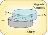
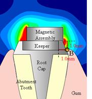
Fig. 1. Structures of sandwich type magnetic attachment.
Fig.1. shows the longitudinal section and the dimension of the magnetic attachment considered here. The shape of magnetic assembly is designed to be a disk with 4.0mm in diameter and 1.5mm in thickness, and a keeper is a disk with 4mm in diameter and 1.0mm in thickness. Magnetization J of the magnet is assumed to be 1.3 T. Keeper is soft magnetic stainless steel with 1.6 T in saturation flux density Bs. Non-magnetic stainless steel is used to protect the magnet from corrosion in the mouth. Leakage magnetic flux has been analyzed by the use of FEM (μ−MF, μ−TEC Co.,LTD.,Tokyo).
The leakage magnetic flux was evaluated by using the WHO’s guideline. The limits of exposure to static magnetic flux for the general public in continuous is 40mT 1)2).
Results and Discussions
1. The leakage magnetic flux of a sandwich type magnetic attachment
Fig. 2. The leakage magnetic flux for the optimized sandwich type magnetic attachment.
Fig.2 shows the leakage magnetic flux for the optimized sandwich type of magnetic attachment at the air gap is 0mm between a magnetic assembly and a keeper, and shows the contour figure when the model is seen from the directions by the arrows. It shows that the largest magnetic flux is 49.4mT at the surface of the magnetic assembly. Because that the magnet is not covered with soft magnetic material. However, the leakage magnetic flux is 22.1mT at the position of 0.4mm away from the surface of the magnetic assembly.
2. The air gap and leakage magnetic flux
(a) Distance from the side cover (b) Distance and leakage flux density
Fig. 3. Leakage flux density V.S. distance from the air gap.
In some clinical cases, a small air gap may come between a magnetic assembly and a keeper in the long term use. It shows the leakage flux when the length of the air gap varied from 0mm to 0.2mm in Fig.3(b).
The leakage magnetic flux becomes large as the gap length. The density doesn’t exceed the WHO’s guideline 40mT when the distance from the air gap is larger than 0.27mm (gap=0mm) and 0.85mm (gap=0.2mm).
3. The shift length and the leakage magnetic flux
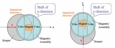
(a) (b)sx (c)sy
Fig. 4. Shift direction of magnetic assembly
In the long term use of the dental prosthesis with the magnetic attachment, a magnetic assembly and a keeper may horizontally shift each other from the proper position. We examined the magnetic flux of two shifted cases such as the direction of X and Y shown in Fig.4(a). The result is shown in Fig. 5.
Fig. 5. Shift and Leakage magnetic flux density
Fig.5. shows that the leakage magnetic flux is different depending on the slipping directions. The marked increase of the magnetic flux within 1mm of the shift length was not seen for direction of y. As for the direction of x, the leakage magnetic flux increases rapidly when the shift length exceeds 0.4mm.
The leakage magnetic flux is 1.27T at the shift length =1.0mm, but Fig.6 shows that it drops below 40mT at the position 1.47mm away from the magnetic assembly (shift length =1.0mm).
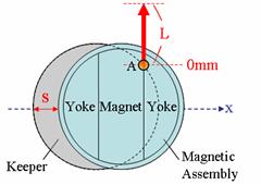
(a) L shows the Distance from A (b) Distance and leakage flux density
Fig. 6. Leakage flux density V.S. distance from A point.
4. Leakage magnetic flux at the alveolar ridge
(a) Conter around the magnetic attachment (b) Shift length and leakage
density
and the
alveolar ridge
Fig. 7. Leakage magnetic flux of the tissue around the magnetic attachment
On the supposition that the shortest distance from the magnetic attachment to the tissue of alveolar ridge is far 1.0mm for horizontal and vertical direction from B point. It is shown that the leakage magnetic flux against the shift length in Fig.7. It also shows the leakage magnetic flux of the cup type magnetic attachment for the comparison. As for the leakage magnetic flux of the sandwich type does not exceed the WHO’s guideline 40mT when the shift length is within 0.9mm. The cup type doesn’t do 40mT even if the shift length is 1.0mm.
Conclusions
The leakage magnetic flux of two types of magnetic attachment becomes large when the gap length between a magnetic assembly and a keeper becomes long. However, it hardly exceed the WHO's guideline 40mT at the position corresponding to the tissue in the mouth. The attention may be needed for the application of sandwich type magnetic attachment, because the leakage magnetic flux of it changes largely depending on the shift direction.
The leakage magnetic flux of the sandwich type of magnetic attachment is larger than that of the cup type, because the magnet of the sandwich type is not completely covered with the yoke which is made of soft magnetic material as the cup type.
References
1. Environmental Health Criteria; 232 STATIC FIELDS: Appendix 1. INTERNATIONAL GUIDELINES ON EXPOSURE TO STATIC MAGNETIC FIEKDS.WHO 2006.
2. Environmental Health Criteria; 232 STATIC FIELDS: 8.1.2 Static magnetic field. WHO 2006.