Fundamental
Investigation About an Optimum Design of Crown and Bridge Made of the Pt-Fe
Magnetic Alloy Using the Integral Element Method : The 4th Report
Nobuki Shoji a, Shinn Kasahara a,
Osamu Okuno b , and Kohei Kimura a
a Division of
Fixed Prosthodontics , Department of Restoration Dentistry, Tohoku
University Graduate School of Dentistry , Sendai , Japan
b Division of
Dental Biomaterials , Department of Restoration Dentistry, Tohoku University
Graduate School of Dentistry , Sendai , Japan
Abstract
The
removable prosthetic appliance makes plaque control easy, comparing with the
fixed prosthetic. However, conventional retainer of removable prosthesis has
problems declining of retention and lowering of esthetic. As a solution, the
removable crown and bridge system assembled with the Fe-Pt magnet outer cap and
the magnetic stainless steel (SUS447J1) inner cap has been investigated
(Fig.1). Using the integral element method, the 3-dimensional magnetic field of
the outer and inner cap model were analyzed to determine the optimal method for
the design and magnetization of removable crown and bridge system made of the
Fe-Pt magnet. The following matters were examined. It was thought that
sectorial four-pole magnetization was the most suitable for magnetization of
the Fe-Pt magnet. In the thickness of outer cap top, the width of shoulder and
the thickness of inner cap top, the thickness of outer cap top had the most
influence on the attractive force. In case of that the thickness of outer cap
top was 1.0mm, 1.5mm, the attractive force indicate optimum clinically.
In
this examination, the influence of material and length of axial surface about
the attractive force was examined. As a result, some findings were obtained.

Fig.1. The schema of the
removable crown and bridge system assembled with the Fe-Pt magnet outer cap and
the magnetic stainless steel (SUS447J1) inner cap.
Objectives
The following were
shown by previous examinations. Using the integral element method, the
3-dimensional magnetic field analysis of the disk model was analyzed to
determine the optimal method for the design and magnetization of removable
crown and bridge system made of the Fe-Pt magnet in the 1st & 2nd reports. As a result, it was
suggested that sectorial four-pole magnetization was the most suitable for
magnetization of the Fe-Pt magnet.
In
the 3rd report, in additional, the optimal design and the method of
magnetization of the outer cap of Fe-Pt magnet and the inner cap of magnetic
stainless steel (SUS447J1) were examined by using the integral element method
of the 3-dimentional magnetic field analyses. The influence of the thickness of
outer cap top, the width of shoulder and the thickness of inner cap top on
attractive force was examined. As
a result, it was suggested that the thickness of outer cap top influenced on
the attractive force most, and that the attractive force inducted optimum
clinically when the thickness of outer cap top was 1.0mm and 1.5mm. About the
outer cap side and the width of shoulder, the outer cap side was magnetization
low. The magnetization magnetic field was distributed when the outer cap was
magnetized. As a results, it were suggested that the attractive force did not
depend on the width of shoulder and that the outer cap side influenced little
on the attractive force.
Therefore, using the
integral element method of 3-dimentional magnetic analyses, the influence of
outer cap side that on the attractive force, the magnetic flux density and the
magnetic leakage flux were examined.
Materials and
method
An
example of the analysis model for the magnetization of the Fe-Pt magnet was
shown in Fig.2.
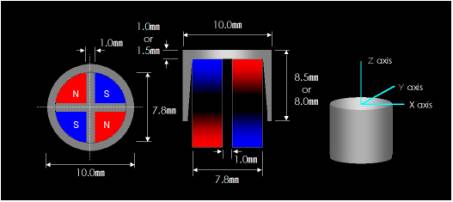
Fig.2. An example of the
magnetization model and the magnetization model feature.
The
permanent magnet was used for magnetizing the Fe-Pt magnet. The sectorial
four-pole magnetization pattern was used to magnetize the Fe-Pt magnet. The maximum diameter of
permanent magnet for magnetization was used as to be contacted to the inside of
outer cap. Each model were axial symmetric, so the 1/4 model was used for this
analysis. Examples of the models for the attractive force, magnetic flux
density and magnetic leakage flux analyses were shown in Fig.3.
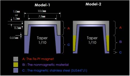
Fig.3. Examples of
analysis models feature.
The magnetized Fe-Pt
magnet model was in contact with the magnetic stainless steel (SUS447J1) model.
And
the attractive force , the magnetic flux density and the magnetic leakage flux
were calculated.
Model-1 is single type. Only the Fe-Pt magnet was used for the outer cap.
Model-2 is combination type. The Fe-Pt magnet and the nonmagnetic material were
used for the outer cap. The dimension of materials of side was shown in
Table1.
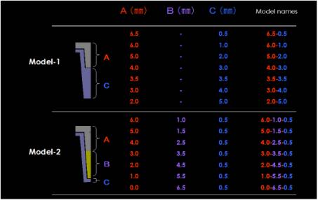
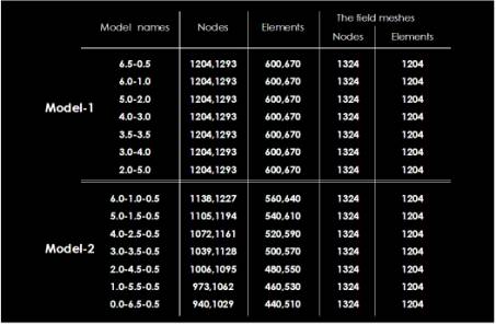
Table1. The dimension of
materials of side.
The
field mesh model for the analysis of the magnetic leakage flux was shown in
Fig.4. The magnetic leakage flux was analysis for the field mesh model of 0-
and 45-degree.
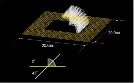
Fig.4. The field mesh
model.
The number of nodes
and elements were shown in Table2.
Table2. The number of nods
and elements of model-1 and model-2.
The magnetic
characteristic value of the Fe-Pt magnet and the permanent magnet for
magnetization obtained by the 2nd report were used.
The following
numerical values was used as the magnetic characteristic of the Fe-Pt magnet, (BH)
max : 16.0MGOe, Hc : 3.7kOe, Br : 11.9kG. The following numerical values was used
as the magnetic characteristic of the magnetic stainless steel (SUS447J1), µm :
100, Bs : 13.5kG.
The following numerical values was used as the magnetic characteristic of the
permanent magnet for magnetization, (BH) max : 11.0MGOe, Hc : 10.5kOe, Br :
11.0kG. And the
permeability of non-magnetic material was set as 1.0.
Results
Fig.5 shows the
analytical results of the attractive force.

Fig.5. The analytical
results of the attractive force.
In model-1, the
attractive force decreased when the length of outer cap side (A) was shorter.
In model-2, when the Fe-Pt magnet side (A) became shorter and the nonmagnetic
material side (B) became longer, the attractive force became lower. The
attractive force of model-2 was lower than that of model-1 in this analysis.
In general, the
attractive force of ready-made magnetic attachment was about 400-600gf, and the
attractive force of Konuskronen was about 500gf. When the
thickness of outer cap top was 1.5mm and the length of outer cap side was
4.0-3.5mm, the optimum attractive force of 400-600gf were obtained clinically. Besides, when the thickness of
outer cap top was 1.0mm and the length of outer cap side was 6.5-5.0mm, the
optimum attractive force were also obtained clinically. The attractive force of
model-1 was more excellent than that of model-2.
Fig.6 and Fig.7 shows
the analytical results of maximum magnetic flux density.

Fig.6. The analytical
results of maximum magnetic flux density of model-1.
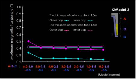
Fig.7. The analytical
results of maximum magnetic flux density of model-2.
The length of Fe-Pt
magnet side became shorter, the maximum magnetic flux density of outer cap
became lower in the model-1. In the model-2, although the length of Fe-Pt
magnet side was change, the maximum magnetic flux density of outer cap has not
changed so much. The maximum magnetic flux density of inner cap has also not
changed so much in model-1 and model-2. As a result, it was suggested that the
model form did not influence on the maximum magnetic flux density of inner cap.
Fig.8 shows examples
of analytical results of the magnetic flux density.
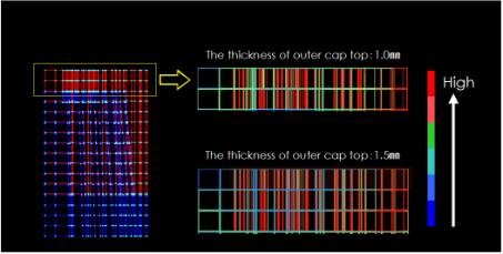
Fig.8. Examples of
analytical results of the magnetic flux density.
When the 1.0mm and
the 1.5mm of outer cap top were compared, it was thought that the latter was
more magnetized in the vicinity of contact side with the inner cap in the side
of outer cap top.
The magnetic circuit
is seemed to close magnetic circuit, besides it influenced on the attractive
force well.
That is, it was
suggested that shorter side of the outer cap influenced little on the
attractive force. From the analytical results of attractive force, when
the occlusal vertical dimension of the molar was low, it was suggested that the
thickness of outer cap top was more important than the length of outer cap
side. Fig.9 shows the analytical results of maximum magnetic leakage flux.
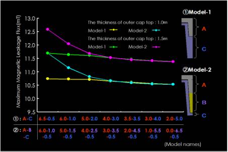
Fig.9. The analytical
results of maximum magnetic leakage flux.
When the thickness of
outer cap top of model-1 was 1.0mm and 1.5mm, the maximum magnetic leakage flux
have not changed so much. The Fe-Pt magnet of model-2 became shorter, the
maximum magnetic leakage flux became lower. The safety standard of static
magnetic field in USA, UK and USSR were 20-30mT. In this analytical results,
the maximum magnetic leakage flux of model-1 was 11.7mT, and the maximum
magnetic leakage flux of model-2 was 12.6mT. From the above-mentioned results,
it was shown that neither models did harm to the human organism. Fig.10 shows examples of analytical results of the magnetic
flux density and the magnetic leakage flux.
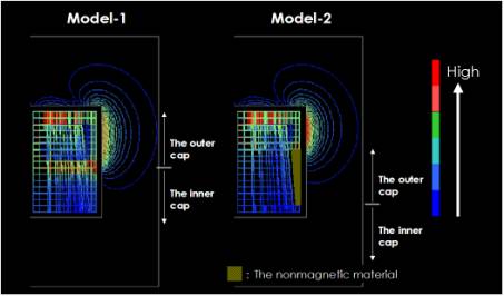
Fig.10. Examples of
analytical results of the magnetic flux density and the magnetic leakage flux.
In model-1, there was
the part where the magnetic flux density was large at the shoulder of outer cap
side. While in model-2, there was no part where magnetic flux density was large
at the outer cap side. Magnetic flux flowed to not nonmagnetic material but the
space on the side of outer cap side. As a result, compared to model-1, it was
thought that the magnetic leakage flux of model-2 became large. And, it was
thought that the magnetic leakage flux influenced the attractive force too.
Conclusion
1. When the thickness of outer cap top was 1.5mm
and the length of outer cap side was 4.0-3.5mm, the optimum attractive force
were obtained clinically. Besides,
when the thickness of outer cap top was 1.0mm and the length of outer cap side
indicated 6.5-5.0mm, the optimum attractive force were obtained clinically.
2.
The attractive force of model-1 was more excellent than that of model-2.
3.
When the occlusal vertical dimension of the molar was low, it was suggested
that the thickness of outer cap top was more important than the length of outer
cap side in both models.