Fundamental
Investigation about an Optimum Design of Crown and Bridge
Made of The Fe-Pt Magnetic Alloy Using The Integral Element Method
The 2nd Report
Nobuki Shoji a, Keisuke Nakamura a, Taro Kanno a, Masanobu Yoda a, Masashi Takahashi c, Koji Kusayanagi d, Kohei Kimura a, and Osamu Okuno b
a Division of Fixed Prosthodontics , Department of Oral Rehabilitation and Material Science , Tohoku University Graduate School of Dentistry , Sendai , Japan
b Division of Dental Biomaterials , Department of Oral Rehabilitation and Material Science , Tohoku University Graduate School of Dentistry , Sendai , Japan
c GC Co. , Tokyo , Japan
d Elf Co. , Osaka , Japan
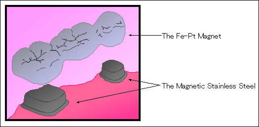
The removable prosthetic appliance makes plaque control easy, comparing with the fixed prosthetic. Therefore, the removable appliance tends to prevent periodontal disease and caries. However, conventional retainer of removable prosthesis has problems calling for the decline of retention and lowering of esthetic. In recent years, the new removable appliances by the permanent magnet have been examined and obtained good results.1) In our laboratory, development of the new removable prosthetic system, which uses the Fe-Pt magnetic alloy have been performing. The attractive force between the Fe-Pt magnet crown and the magnetic stainless steel cap (SUS447J1) is utilize for the retention of the crown in this system(Fig.1).

Fig.1 Application of the Fe-Pt magnet to removable prosthetic appliance.
It was reported that the Fe-Pt magnetic alloys were able to cast using the dental casting machine.2) Composition of the Fe-Pt magnetic alloys used for an outer cap is Fe, 39.5 mol% Pt, and very small amount of Nb and Si.2,3,4,5) The casting of the magnetic alloy showed adequate attractive force in clinical applications.4,5)
In the present work, using the integral element method, the 3-dimensional magnetic field of the disk model was analyzed to determine the optimal method for the design and magnetization of removable crown bridge system.
The attractive force of the Fe-Pt magnet disk by dental casting and the magnetic stainless steel disk (SUS447J1) was investigated, and the result was compared to the analysis by the integral element method. Reliable calculation conditions for the 3-dimentional magnetic field analysis by the integral element method were discussed.
The Fe-Pt magnet used for this experiments were Fe-39.5mol% Pt-0.65mol% Nb-0.1mol% Si. They were prepared from 99.995% electrolytic iron (ATOMIRON-MP, Toho Zinc Co., Ltd., Japan), 99.9% platinum (Tanaka Kikinzoku Kogyo K. K., Japan), 99.9% niobium, and 99.5% silicon. The magnetic stainless steel was SUS447J1. An argon arc furnace (TAM-4S, Tachibanariko Co. Ltd., Japan) in 99.9999% argon gas was used to make the magnetic alloy. To produce a homogeneous alloy, the metals were alternately inverted and melted at least four times. The Fe-Pt magnetic alloy was cast into the mold (Titavest CB, Morita Co. Ltd., Japan), using a high frequency melting vacuum pressure casting machine (Argoncaster T, Shofu Inc., Japan) at mold temperature of 600℃. The surfaces of the casting specimens were polished, using an automatic lapping and polishing machine ( MA-200, Musashinodenshi, Japan ) and cleaned with acetone in an ultrasonic cleaner. Subsequently, the specimens were vacuum-sealed in the silica tube and then heated for the solution treatment and the aging. After the heat treatment, the specimens were magnetized with a static field of 16kOe for 50μs. The dimension of the specimens is shown in Figure2.

Fig.2 The dimension of the specimens.
The attractive force between the magnetic stainless steel (SUS447J1) and the Fe-Pt magnet was measured by universal testing machine (Autograph IS500, Shimadzu, Japan). Cross-head speed of 2.5mm/min was used. Each specimen was measured four times. The maximum value was adopted as the attractive force of the Fe-Pt magnet.
The surface inductive flux of the Fe-Pt magnet was measured by Gauss meter. The maximum value was adopted as the surface inductive flux of the Fe-Pt magnet.
The hysteresis curve of the Fe-Pt magnetic alloy was measured by VSM. The direction of measurement of the magnet properties is shown in Figure3. The saturation flux density (Bs), residual flux density (Br), coercive force (Hc) and the maximum energy product ( (BH)max ) were calculated from the hysteresis curves. The hysteresis curve of the magnetic stainless steel, which had been measured in the last paper6), was used in this report. Permeability and Saturation flux density were calculated from the hysteresis curve. These values were used for the 3-dimentional magnetic field analysis.
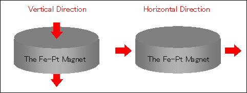
Fig.3 The measurement direction of the magnetic properties.
The attractive force was calculated by the 3-dimenthinal magnetic field analysis, using the integral element analysis software package, "ELF/MAGIC" (ELF Co., Japan) . The number of nodes and elements is shown in Table 1. Analysis models are shown in Figure4.
Table 1 Number of nodes and elements of the 3-dimentional magnetic field analysis.
| Number of nodes | Number of elements | |
| The Fe-Pt Magnet | 390 | 240 |
| The Magnetic Stainless Steel | 441 | 400 |
| The Permanent Magnet for Magnetization* | 118 | 43 |
* This magnet is hypothetically used in the calculation for magnetization by the integral element method.
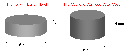
Fig.4 Analysis models.
The analysis model for the magnetization of the Fe-Pt magnet is shown in Figure5. A magnetic characteristic used the following numerical values, (BH)max : 2, 4, 6, 8, 10, 12, 14, 16, 18, 20, 22, 24 MGOe, Hcb : 8.8 kOe, Br : 9 kG. Figure6 shows the model of the attractive force analysis.

Fig.5 The model for the magnetization analysis.
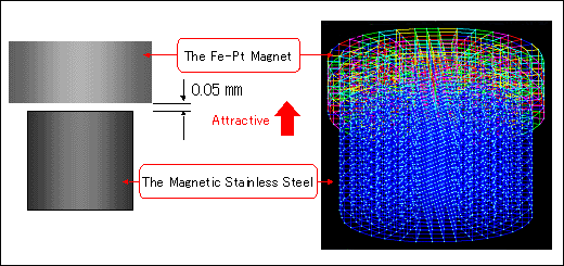
Fig.6 The model for the attractive force analysis.
Figure7 is the scatter chart of the measurement surface inductive flux of the Fe-Pt magnets and the measurement attractive force of the Fe-Pt magnets. There was positive correlation between the surface inductive flux and the attractive force of the Fe-Pt magnets. The correlation coefficient in the N pole was 0.78 and, in the S pole, 0.80.
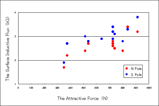
Fig.7 Scatter chart of the measurement surface induction of the Fe-Pt magnet and the measurement attractive force of the Fe-Pt magnet.
Figure8 is the scatter chart of the measurement maximum energy product of the Fe-Pt magnet and the measurement attractive force of the Fe-Pt magnet. There was a positive correlation between the maximum energy product and the attractive force. The correlation coefficient in the vertical magnetic property was 0.77 and, in the parallel magnetic property, 0.76. The demagnetization curves almost became similar figures.

Fig.8 Scatter chart of the measurement maximum energy product of the Fe-Pt magnet and the measurement attractive force of the Fe-Pt magnet.
Figure 9 is shown analytical attractive force of the Fe-Pt magnet in four test pieces and analytical (BH)max of the permanent magnet for magnetization.
When the maximum energy product of a permanent magnet for magnetization was 14.7-17.2MGOe, the analytical attractive forces of the Fe-Pt magnet corresponded to the measured attractive forces of the Fe-Pt magnet.
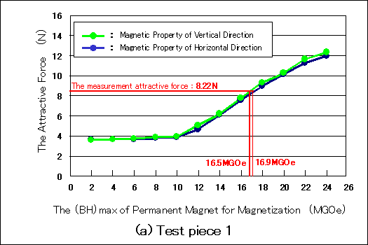

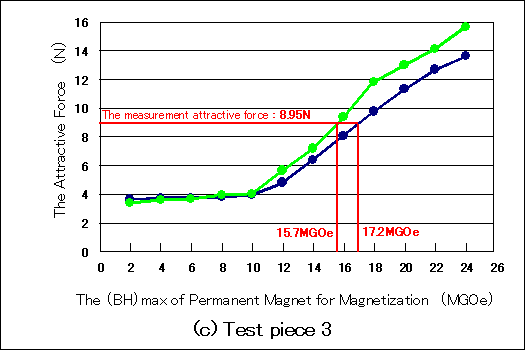
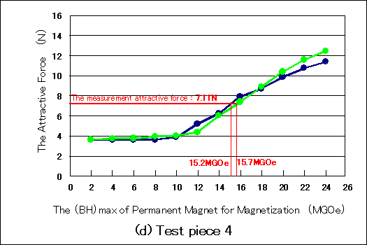
Fig.9 Analytical attractive force of the Fe-Pt magnet in four pieces and analytical (BH)max of the permanent magnet for magnetization.
Figure 10 shows the relationship between (BH)max of the Fe-Pt magnet and (BH)max of the permanent magnet for magnetization*.
Average (BH)max of the Fe-Pt magnet was 16.0MGOe(SD= 0.85). Average (BH)max of the permanent magnet for magnetization was 11.0MGOe(SD=2.13 ). When the average (BH)max of the Fe-Pt magnet and the average (BH)max of the permanent magnet for magnetization were used for designing the removable crown bridge by the integral element method, optimal removable crown bridge system by Fe-Pt magnet might be accomplished.
* This magnet is hypothetically used in the calculation for magnetization by the integral element method.
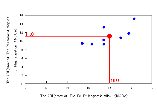
Fig.10 The relation between (BH)max of the Fe-Pt magnet and (BH)max of permanent magnet for magnetization.
1. A positive correlation was observed between the attractive force and the surface inductive flux.
2. A positive correlation was observed between the attractive force and the maximum energy product.
3. When the average (BH)max of the Fe-Pt magnet (16.0MGOe) and the average (BH)max of the permanent magnet for magnetization (11.0MGOe) were used for designing the removable crown bridge by the integral element method, the optimal removable crown bridge system by Fe-Pt magnet might be accomplished.
1) Tutui, H., Kinouchi, Y., Shiota, M. : Study on the Sm-Co Magnet as a Dental Material. J Dent Res 58 : 1597-1606 , 1979.
2) Kanno, T., Yoda, M. and Kimura, K. : An application of Fe-Pt-Nb magnet to crown and bridge prosthodontics. J J Mag Dent 5(1) : 58-66 , 1996. (in Japanese)
3) Nakayama, T., Watanabe, M. and Homma, M. : Magnetic properties of hard magnetic Fe-Pt alloys in dental casts. J Magn Soc Jpn 21 : 377-380 , 1997. (in Japanese)
4) Kanno, T., Nakayama, T. and Kimura, K. : Effects of Si and Nb on Fe-Pt magnetic alloys. J J Dent Mater 17(1) : 54-61 , 1998. (in Japanese)
5) Kanno, T., Nakayama, T. and Okuno, O. : Basic investigation of Fe-Pt-Nb magnetic alloys to removable crowns and bridges by casting. J Jpn Prosthodont Soc 42(3) : 424-430 , 1998. (in Japanese)
6) Aida, K., Haoka, K., Kanno, T., Yoda, M., Kimura, K. : A study on dental casting of magnetic stainless steel. -magnetic properties and attractive force- J J Mag Dent 9(1) : 11-16 , 2000. (in Japanese)