Attractive Force Analysis of
Implant Magnetic Keeper using Three-Dimensional Finite Element Method
−
The effect of surface screw hole pattern design for magnetic attachments −
H. Kumano, T. Masuda, Y. Nakamura, R. Kanbara, T. Iwai,
Y. Ohno, K. Yoshihara, Y. Tanaka
Department of Removable Prosthodontics,
School of Dentistry, Aichi-gakuin University
Introduction
The
clinical applications of magnetic attachments with implant overdentures has become more common with progressive
advances in implant materials and methods of use. The use of the magnetic
attachments non-mechanical retentive design and an ease of concealment helps to
reduce lateral forces and results in the controlled load transfer to a
supporting abutment. The application and use of magnetic attachments with
dental implants permits prosthetic flexibility in implant location and
orientation, helping the overall esthetic outcome.
An implant magnetic attachment is secured to a implant fixture using a retaining screw. All screw designs require a superior surface access hole on the the magnetic keeper for placement and removal. These keeper screw access holes used may be of different dimensions depending upon the proprietary instrument size requirements for each design. Few studies are available regarding the influence of a screw hole on attractive force. The finite element method is an effective method for the solution of problems with non-linear material behaviors. The dynamics of a magnet interior is visualized by using this method, and permits simulation under changing conditions.
Objective
The purpose of the present study was to analyze the effects of differential screw access hole dimensions to an implant keeper upon attractive force and magnetic field using the three-dimensional (3D) finite element method.
Materials and Methods
1. Analysis
model
Figure 1 shows
a implant keeper prototype used as a reference of the analysis model.
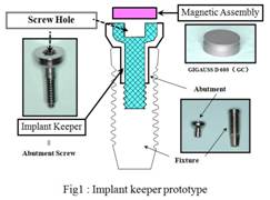
An abutment screw is made of
magnetic stainless steel, and serves as an implant keeper. An abutment is fixed
to the fixture with this screw. A screw hole is located in the center of a
keeper. The magnetic assembly is designed to adhere to a magnetic attachment
(GIGAUSS D 600; GC). Interior configuration of a magnetic assembly was measured
prior to modeling procedures. Actual and proprietary measurements of an
attachment were compared to estimate the external shape of the attachment.
Internal configuration data was also required for modeling, but was not
available. The sample attachment was embedded, sectioned using a diamond
cutter, and then internally measured using VF-7510 to determine internal shape
and measurement configurations. Figure 2 shows measurements of a magnetic
assembly.
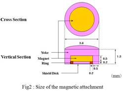
The magnet embedded in the
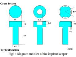
assembly was a round-shape configuration. Secondly, three keepers with
different screw hole locations including a keeper
without a screw hole, a keeper with a screw hole in the center, and a keeper
with a screw hole in the edge were designed. Figure 3 shows a diagram and size
of an implant keeper designed in the present study.
An analysis model was constructed
using Femap (UGS), and μ-MF (μ-TEC) was used for the
analysis. Identical element count and nodal point were used for all models. The
element type designation was three-dimensional pentahedral
and hexahedral elements. Figure 4 shows a constructed finite element model.
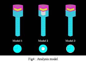
A quarter model
was created for the purpose of evaluating axial symmetry. Analysis range was
peripheral 3 mm of a keeper and magnetic assembly. An element breakdown was
conducted. A keeper without a screw hole,a keeper
with center screw hole, and a keeper with a edge access screw hole are referred
to as Models 1, 2, and 3, respectively.
1. Analysis
condition
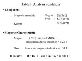
The
magnetic property value was determined based on the thermal property of the
test magnet (GIGAUSS D 600) obtained from a prior study and compared with
proprietary information. (Miyata et al.) Although
fabrication of the original yoke and keeper material is of SUSXM 27 alloy, the
proprietary information is not released nor available.
Similar steel property values were thus selected for functional similarity of magnetic
properties. (SUS447J1 steel material) As the SUS447J1 steel material values
were assigned, B-H curve was then approximated and selected, for designation of
magnetic properties (Table 1). Analysis results were evaluated in terms of magnetic
flux density distribution and attractive force.
Results
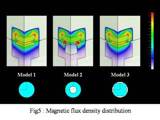
1. Magnetic flux density distribution
Figure 5 shows the magnetic flux density distribution. No significant difference in the magnetic flux density distribution inside a magnetic assembly was observed. However, on the adhesive surface between a magnetic assembly and a keeper, a high magnetic flux density was observed around the Model 2 screw hole. As for a magnetic flux density inside a keeper, a magnetic flux distribution extended to the inferior part of a keeper in Models 1 and 3.
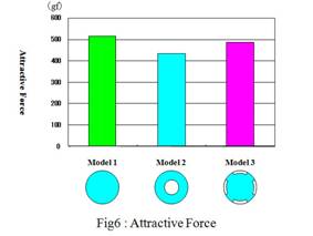
2. Attractive
force
Figure
6 shows an attractive force of each model. An attractive force was the highest
in Model 1 (520 gf), followed by Model 3 (490 gf), and Model 2 (440 gf). Attractive
force decreased by 16% in the Model 2 with a screw hole in the middle, and 6%
in the Model 3 with a screw hole in the edge compared to the Model 1 without a
screw hole.
Discussions
Although
magnetic forces and magnetic fields can be measured using specialized measuring
devices, it is difficult to design a magnet for maximum magnetic force based
solely these values, and to also verify optimal properties with minimal field
leakage. The finite element method is an effective way to examine some of these
various issues.
Since
the space has a magnetic distribution, an integration path of the space around
the analysis model and also the interface between the magnetic assembly and
keeper needs to be subdivided for evaluation. A preliminary analysis was
performed to calculate figures with minimal influence. A subdivided analysis is
considered very accurate for these purposes.
The
magnetic properties of the magnetic stainless steel and magnet are important
for the analysis. However, the detailed magnetic properties are unknown.
Therefore, the SUS447J1 steel material values that have similar magnetic
properties as SUSXM27 were assigned. The B-H curve was approximated from these
values and used in the analysis. Future challenges lie in accurate value measurement
and a search for materials with closer magnetic properties as SUSXM27.
The
magnetic assembly used in the present analysis was cup yoke type. Magnetic flux
density concentrates on the center of a keeper adsorption surface in this type
of assembly. The air apace layer in the non-magnetic area screw hole blocks the
magnetic flux, and creates high magnetic flux distribution in the surrounding
area, resulting in the oversaturated magnetic flux density distribution of the
keeper in the Model 2 compared to the Model 1. In the Model 3 which has a screw
hole in the edge, magnetic flux was not blocked due to the side location of a
screw hole. Therefore, the magnetic flux distribution of the Model 3 was the
same as Model 1.
Attractive force is calculated by square
magnetic flux density and facing area. The Model 2 with a screw hole in the
center showed the biggest decrease in attractive force. This is considered to
be due to a decrease in facing area and oversaturated magnetic flux density
around a screw hole. In the Model 3 with a screw hole in the edge, a decrease
in the attractive force was suppressed despite a decrease in the facing area.
This is considered to be due to the small influence of the magnetic flux
density inside the keeper. It has been reported that a decrease in attractive
force can be prevented by making a screw hole smaller in the Model 2. Further
analysis is required to obtain optimized implant keeper configuration.
Conclusions
An
influence of the screw hole configuration on an
implant abutment attachment magnetic keeper surface was analyzed using
three-dimensional finite element method, and the following results were
achieved.
1. Oversaturated
magnetic flux density was observed inside a keeper around a screw hole in the
model with a screw hole in the middle.
2. Attractive
force decreased by 16% in the model with a screw hole in the center, and 6% in
the model with a screw hole in the edge compared to the model without a hole.
References
1. Tanaka, Y. : Dental Magnetic Attachment, Q&A, Ishiyaku Publishers, Inc (Tokyo), 1995.
2. Nakamura, Y. Tanaka, Y. Ishida, T. and et al : Dynamic Analysis of a Magnetic Attachment using Finite Element Method –Comparison of the two dimensional analysis with the three dimensional one-. J J Mag Dent.8:57-62,1999
3. Miyata, T. Niimi, J. Ando, A. and et al : Influence of heating of a magnetic attachment on the attractive force. J J Mag Dent.17:44-50,2008