Retentive force and Magnetic flux leakage of small sized keeper
C. Nagoya1, Y. Umekawa1,2,
T. Ishigami1,2, O. Kujirai3, H. Toyoma1,2, M. Takamura1, M. Tsuyumu1 and
1Department of Partial Denture Prosthodontics, Nihon University School of Dentistry
2Division of Clinical Research,
3GC Corporation
Introduction
Dental magnetic attachments of various types and sizes that have
satisfactory retentive force and stability are now commercially available1,2. From among the various sizes of magnetic
attachments available, the magnetic attachment is usually selected according to the size and shape of cross-section of the
retained root3,4. Additionally, there are some
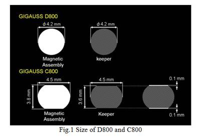
difficulties to apply circle formed attachment to a shaped root with an elliptical cross-section. Following
to this clinical problem, GC produced a new magnetic attachment GIGAUSS
C800 (C800). This minor axis of keeper is 0.2 mm smaller than the corresponding
magnetic attachment.
Objective
This study sought to
evaluate the retentive force and magnetic flux leakage of C800, as compared
with D800.
Materials and Methods
The magnetic attachments used in this study and the equipments are presented in Table 1.
Two cylindrical magnetic assemblies, GIGAUSS C800 (C800; GC,
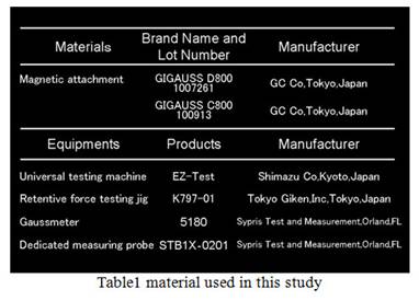
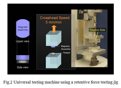
Retentive
force was measured in a universal testing machine (EZ-TEST; SHIMADZU Co,
Magnetic
flux leakage was measured using a Gaussmeter (F.W
Bell 5180; Sypris Test and Measurement, Orlando, FL) and dedicated measuring
probe (Ultra Thin Transverse Probe STB1X-0201; Sypris Test and Measurement,
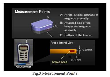
Orlando, FL); Tektronix Services Solutions (Table I). Ten measurements (2 groups × 5
measurements), were made at 3 points: A, at the outside interface of the keeper
and magnetic assembly; B, beside the keeper; and C, at the bottom of the
keeper. The probe has an active area that is located 0.3 mm from the tip
surface, and the measurement was performed when the probe was in contact with
the specimen (Fig. 3).
Data were analyzed with a
1-way analysis of variance (ANOVA), and differences between the groups were
analyzed with Tukey’s Honestly Significant Difference
(HSD) post hoc test (α = .05).
Results
The
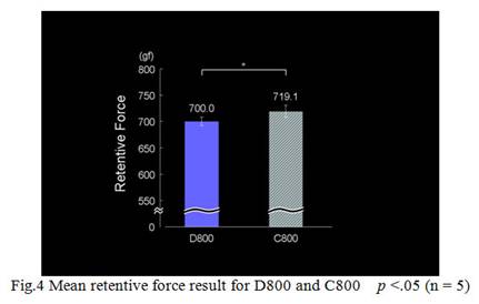
mean retentive force was 700.0 gf for D800 and 719.1 gf for C800. C800 was significantly higher than D800 (p <.05) (Fig. 4).
The
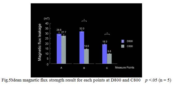
results for magnetic flux leakage are shown in Figure 5. D800 of
magnetic leakage was significantly higher at B than at A and C (p<.05). C800 of magnetic flux
leakage showed significantly higher at A than at B and C (p <.05). At the measurement point of A on D800, the mean
magnetic flux leakage was 29.8 mT and at the point of
A on C800 was 27.7 mT, there was no significant
different between D800 and C800 (p <.05).
At the measurement point of B, the mean magnetic flux leakage was 32.0 mT for D800 and 14.6 mT for C800,
(p<.05). C800 showed significantly
lower magnetic flux leakage at B (p <.05).
Discussions
Any
deleterious effects on marginal tissues have not been reported, however, there
is a need to clarify how the long-term use of magnetic attachments in the oral
area might affect patients. The magnetic flux strength decreased in proportion
to the square of the distance. As the magnetic attachment is not attached
directly to oral tissue because the keeper is attached to a structure composed
of metal dental materials, there is sufficient distance from the magnetic
attachment to the marginal gingival tissue.
The results indicated that C800 has stronger attractive force, and C800 is lower magnetic flux leakage than D800 at every measurement points, nevertheless C800 has smaller keeper than D800. This considerable reason for these results in this study is differences in shapes of C800 and D800 magnetic assemblies. D800 and C800 have undercut groove for retention. However, circle shaped D800 needs higher retention than elliptic shaped C800. Therefore, the undercut of D800 is bigger than C800. It seems like this groove effect of the magnetic circuit.
Furthermore, the tendency of the magnetic flux at C800 is large at upper surface of the magnetic assembly, in contract to C800, D800 of the magnetic flux is large at attached side of the keeper and magnetic assembly, where is the marginal gingival tissue area. In this study, both C800 and D800 of magnetic field leakage at 0.03 mm from the magnetic assembly were not above 40 mT, and, therefore, its recommended usage should not adversely affect the human body. Anyway, C800 is lower magnetic flux leakage than D800 at every measurement points. Magnetic assembly has undercut area for retention. Undercut area of D800 is bigger than C800.It is suggested that undercut area of C800 had better magnetic circuit than D800, therefore, C800 has lower magnetic flux and stronger attractive force.
Taken together, the retentive
force and magnetic flux leakage of C800, this now attachment GUGAUSS C800 is
useful to apply for a lot of clinical situations.
Conclusions
Within the limitations of this study, the
following conclusions were drawn:
1.
Retentive force of GIGAUSS C800 was higher than D800.
2. Magnetic flux strength of GIGAUSS C800 was lower than D800.
References
1. Sasaki H, Kinouchi
Y, Tsutsui H, Yoshida Y, Karv
M, Ushita T.Sectional
prostheses connected by samarium-cobalt magnets. J Prosthet
Dent 1984;52:556-8.
2. Akaltan F, Can G. Retentive characteristics of different
dental magnetic systems. J Prosthet Dent 1995;74:422-7.
3. Maeda
Y, Nakao K, Yagi K, Matsuda
S. Composite resin root coping with a keeper for magnetic attachment for
replacing the missing coronal portion of a removable partial denture abutment.
J Prosthet Dent 2006;96:139-42.
4. Boeckler AF, Morton D, Ehring C, Setz JM. Mechanical properties of magnetic attachments for removable prostheses on teeth and implants. J Prosthodont 2008;17:608-15.