Laser welding between the magnetic stainless steels and titanium as a shield-ring and spacer material
Yukyo Takada, M. Takahashi, Jun Shiroto, A. Kikuchi1 and M. Kikuchi
Division of Dental Biomaterials,
1 NEOMAX ENGINEERING Co.,Ltd.,
Introduction
The non-magnetic stainless steel, SUS316L, is used as a shield-ring or spacer material to form a magnetic circuit in closed magnetic circuit attachments, however it contains nickel. Considering recent global movement for nickel, it is desirable to find nickel-free non-magnetic materials in substitution for SUS316L.
Requirements for the shield-ring and spacer materials contain many factors such as non-magnetism, excellent corrosion resistance, good workability, and so on. The shield-ring or spacer is usually welded to yokes made of magnetic stainless steels such as SUS444, SUSXM27, and SUS447J1 by laser beam. Weldability is one of the important factors for the magnetic attachments because the complete weld is able to seal a corrosive rear earth magnet core and to avoid saliva leaking into inside.
Objective
In this study, we focused on pure titanium as a nickel-free material used for the shield-ring and the spacer, and examined its weldability to the magnetic stainless steels by the laser welding.
Materials and Methods
1. Materials
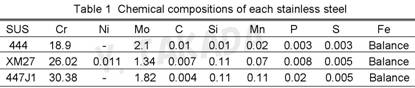
SUS447J1, SUSXM27 and AUM20 (comparable to SUS444) were chosen as the magnetic stainless steels which are used in commercially produced magnetic attachments. Pure titanium (Grade 1) and gold (>99.99 mass%) were also used. The composition of the stainless steels was shown in Table 1.
Methods
1.1 Specimens
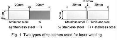
Each stainless steel and titanium sheet were cut and shaped with the size of 5 mm x 20 mm x 0.7 mm. They were polished with #180-600 grid emery papers. Especially, a welded part of the edge was polished carefully at right angle to the surface. Titanium was rolled to a thin sheet at a thickness of 0.3 mm, and shaped with the size of 5 mm x 0.7 mm.
Two types of specimen were used as shown in Fig. 1. The first type was a couple of each stainless steel and titanium pieces (5 mm x 20 mm x 0.7 mm). Another type was a couple of each stainless steel piece that wedged the titanium thin ribbons between them.
1.2 Laser welding
The YAG laser machine
(ALS100, ALPHA LASER
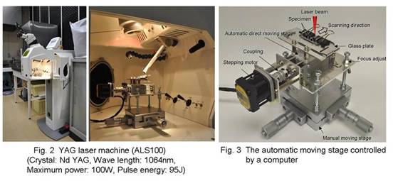
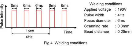
The boundaries between each stainless steel and titanium pieces were welded using the YAG laser machine (n=5) with spraying with Ar gas. In the case of the titanium thin ribbons that were wedged between a couple of each stainless steel piece, the sandwiched lines were also welded by the same way (n=5). The welding conditions were shown in Fig. 4.
1.3 Evaluations
Weldability between titanium and each stainless steel was evaluated by simple methods of a bending test and observation of the welded zone using an optical microscope.
Results
The welded specimens and zones between titanium and each stainless steel were shown in Figs. 5-7. When titanium was welded with each stainless steel, some large cracks were observed on the beads. The running cracks passed into inside of the beads as shown in the cross-section of the beads between titanium and 447J1 the stainless steels (Fig.7).
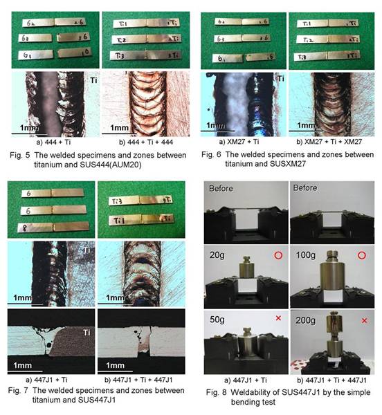
The results by the simple bending test were shown in fig.8. All of welded zone broke down easily. In the case of the thin titanium ribbon wedged between the stainless steels, the bending load below 200g also destroyed all of the sandwich line.
Discussions
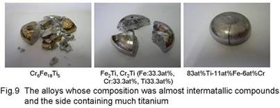
According to the ternary phase diagram of Fe-Cr-Ti system1), formation of hard and brittle intermetallic compounds apparently caused the large cracks and weakened the weld zone. Probably, the composition containing less titanium causes phases including the intermetallic compounds of Cr6Fe18Ti5, Fe2Ti, or Cr2Ti. When we made alloys that were almost the intermertallic compounds (Cr6Fe18Ti5 and 33.3at%Ti-33.3at%Fe-33.3at%Cr alloys) and tapped them with hammer, they broke easily (Fig.9). However, an alloy containing much titanium, a 83at%Ti-11at%Fe-6at%Cr alloy showed a little ductility since it might had meta-stable b phase because of b phase at high temperature (Fig.9).
If much titanium can melt into the bead, a meta-stable b phase possibly forms in the bead and adds ductility to the weld zone.
Conclusions
Although titanium has the hurdle to control the composition of the bead, the meta-stable b phase in the bead possibly takes a chance to improve weldability between titanium and magnetic stainless steels.
References
1. Villars A., Prince A. and Okamoto H., Handbook of Ternary Alloy Phase Diagrams, ASM international, 1997.